Installation Manual GEN20AD-E GEN16AD-E GEN15ADC-E Generator Systems Questions? Help is just a moment away! Call: Generator Helpline 877-369-9400 Monday-Friday 8:00 AM to 5:00 PM Central Time
Thank you for purchasing this quality-built Rheem / Ruud standby generator. We are pleased that you’ve placed your confidence in the Rheem or Ruud brand. When operated and maintained according to the instructions in this manual, your Rheem / Ruud generator will provide many years of dependable service. This manual contains safety information to make you aware of the hazards and risks associated with standby generators and how to avoid them.
Table of Contents Important Safety Instructions. . . . . . . . . . . . . . . . . . . . . . . . 4 Installation . . . . . . . . . . . . . . . . . . . . . . . . . . . . . . . . . . . . 7 Owner Responsibilities. . . . . . . . . . . . . . . . . . . . . . . . . . . . . . . . . . . . . . . . . 7 Installing Dealer/Contractor Responsibilities . . . . . . . . . . . . . . . . . . . . . . . . 7 Cold Weather Kit . . . . . . . . . . . . . . . . . . . . . . . . . . . . . . . . . . . . . . . . . . . . .
Save These Instructions Important Safety Instructions SAVE THESE INSTRUCTIONS - This manual contains important instructions that should be followed during installation and maintenance of the generator and batteries. Safety Symbols and Meanings Explosion Fire Electrical Shock Toxic Fumes Rotating Parts Hot Surface WARNING Running engine gives off carbon monoxide, an odorless, colorless, poison gas.
t t t t t t WARNING Propane and Natural Gas are extremely flammable and explosive, which could cause burns, fire or explosion resulting in death, serious injury and/or property damage. Install the fuel supply system according to NFPA 37 and other applicable fuel-gas codes. Before placing the generator into service, the fuel system lines must be properly purged and leak tested. After the generator is installed, you should inspect the fuel system periodically. NO leakage is permitted.
t t t t t t t t t t t WARNING Exhaust heat/gases could ignite combustibles or structures resulting in death, serious injury and/or property damage. Contact with muffler area could cause burns resulting in serious injury. DO NOT touch hot parts and AVOID hot exhaust gases. Allow equipment to cool before touching. Exhaust outlet side of weatherproof enclosure must have at least 5 ft. (1.5 m) minimum clearance from any structure, shurbs, trees or any kind of vegetation.
Installation Installing Dealer/Contractor Responsibilities Equipment Description This product is only for use as an optional generator system which provides an alternate source of electric power and to serve loads such as heating, refrigeration systems, and communication systems that, when stopped during any power outage, could cause discomfort or inconvenience.
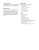
Unpacking Precautions The unit is shipped ready for installation. Avoid damage from dropping, bumping, collision, etc. Store and unpack carton with the proper side up, as noted on the shipping carton. Delivery Inspection After removing the carton, carefully inspect the generator for any damage that may have occurred during shipment.
Installation Checklist Proper installation of the home generator requires the completion of the following tasks: Carbon Monoxide (CO) Detector Carbon Monoxide (CO) detector installed and in working order. Smoke detector(s) installed and in working order. Placement Required permits have been obtained. Generator placed in an area free from Carbon Monoxide (CO) buildup. See Placement of Standby Generator to Reduce the Risk of Carbon Monoxide Poisoning. Generator placed in an area compliant to NFPA 37.
Intentionally Left Blank 10
Generator Placement Before installing generator, consult with home owner and convey the following requirements, which must be satisfied before the installation is complete. There are two equally important safety concerns in regards to carbon monoxide poisoning and fire. There are also several general location guidelines that must be met before the installation in considered complete. WARNING Running engine gives off carbon monoxide, an odorless, colorless, poison gas.
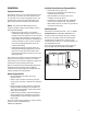
Placement of Standby Generator to REDUCE THE RISK OF CARBON MONOXIDE POISONING The arrows in the figure below point to POTENTIAL points of entry for Carbon Monoxide Gas. EE FF C C B B D D All fossil fuel burning equipment, such as standby generators, contains carbon monoxide (CO) gas in the engine exhaust. CO gas is odorless, colorless and tasteless and is unlikely to be noticed until a person is overcome.
t %JSFDU UIF TUBOECZ HFOFSBUPS FYIBVTU BXBZ GSPN PS parallel to the building or structure. DO NOT direct the generator exhaust towards a potentially occupied building, structure, windows, doors, ventilation intakes, soffit vents, crawl spaces, open garage doors or other openings where exhaust gas could accumulate and enter inside or be drawn into potentially occupied building or structure. t %0 /05 QMBDF TUBOECZ HFOFSBUPS JO BOZ BSFB XIFSF leaves or debris normally accumulates.
Placement of Standby Generator to REDUCE THE RISK OF FIRE Requirements: NFPA 37 2010, section 4. 1. 4, Engines Located Outdoors. Engines, and their weatherproof housings if provided, that are installed outdoors shall be located at least 1.5m (5 ft) from openings in walls and at least 1.5 m (5 ft) from structures having combustible walls. A minimum separation shall not be required where either of the following conditions exist: 1.
Generator Installations NOTICE The figures below demonstrate the minimum installation distances allowed to structures and items shown in legend. A A A 18 in. (45.7 cm) min. 5 ft (1.5 m) 5 ft (1.5 m) Exhaust Direction Standby Standby 5 ft (1.5 m) 5 ft (1.5 m) Exhaust Direction B B A A 18 in. (45.7 cm) min. 18 in. (45.7 cm) min. 5 ft (1.5 m) Standby Standby Exhaust Direction 5 ft (1.5 m) Exhaust Direction B 5 ft (1.5 m) A A B Legend for Generator Locations to reduce the risk of fire.
Electrical and Fuel Inlet Locations The 3/4 inch N.P.T. fuel inlet connector (A) and electrical inlet location (B) is shown below. A ½ inch knock-out is provided for the electrical inlet. This inlet may be enlarged or supplemented to accommodate a maximum conduit size of 1 ½ inches. Ensure that the installed conduit(s) enter the unit in the zone shown in the drawing such that they properly enter the electrical box and do not interfere with the fully opened roof.
Lifting the Generator t t t t WARNING Hazardous Voltage - Contact with power lines could cause electric shock or burns, resulting in death or serious injury. Lifting Hazard / Heavy Object - Could result in serious injury. If lifting or hoisting equipment is used, DO NOT contact any power lines. DO NOT lift or move generator without assistance. Use lifting pipes as described in Lifting the Generator. DO NOT lift unit by roof as damage to generator will occur.
Access Ports The generator is equipped with an enclosure that has several access panels, as shown.
To open roof: 1. Insert key into lock (A) of front panel. Gently push down on roof above the lock to aid in turning the key. Turn key one quarter turn clockwise. 2. Lift roof to the open position. To remove rear panel: 1. Ensure the roof is in the open position. 2. Remove the two bolts (C) that secure the panel to the unit. C To remove front panel: 1. Remove the two bolts (B) that secure the panel to the unit. B A 2. Lift panel to remove from unit. To secure front panel: 1. Place panel in unit. 2.
The Gaseous Fuel System The information below is provided to assist gaseous fuel system technicians in planning installations. In no way should this information be interpreted to override applicable fuel gas codes. Consult with your local fuel supplier or Fire Marshall if questions or problems arise. WARNING Propane and Natural Gas are extremely flammable and explosive, which could cause burns, fire or explosion resulting in death, serious injury and/or property damage.
Fuel Consumption Estimated fuel supply requirements at half and full load for natural gas and LP vapor fuels are shown below. Cu Ft/Hr 3/4 Load 1/2 Load 1/4 Load Exercise 20kW 17kW 15kW 135 118 109 3.75 3.28 3.03 BTU/Hr 337500 295000 272500 Cu Ft/Hr 109 99 90 Gal/Hr (liquid) 3.03 2.75 2.5 BTU/Hr 272500 247500 225000 Cu Ft/Hr 83 74 68 Gal/Hr (liquid) 2.31 2.06 1.89 BTU/Hr 207500 185000 170000 Cu Ft/Hr 56 54 51 Gal/Hr (liquid) 1.56 1.5 1.
Fuel Conversion The engine of your generator system is factory calibrated to run on natural gas (NG) or on liquefied petroleum (LP) vapor. To convert to either fuel, follow these steps: NOTICE Units are set to NG at the factory. 1. Insert key into lock of front panel. Gently push down on roof above the lock to aid in turning the key. Turn key one quarter turn clockwise. 2. Lift roof to the open position. 3. Press the control board OFF button. 4. Remove 15 Amp fuse from control panel. 5.
System Connectors Low Voltage connections to signal fault contacts, transfer switch communication and auxiliary 12VDC power are made via a field connection terminal block in control board area. Compare this illustration with your generator to familiarize yourself with the location of these connections.
Generator AC Connection System A single-phase, three-wire AC connection system is used in the home generator. The stator assembly consists of a pair of stationary windings with two leads brought out of each winding. The junction of leads 22 and 33 forms the neutral lead, as shown schematically and as a wiring diagram. A complete schematic and wiring diagram can be found later in this manual. NOTICE Neutral is not bonded to ground at generator.
Grounding the Generator Generator Power Connection The home generator must be installed as part of a system that includes a listed transfer switch, with neutral to ground bonding at the transfer switch in accordance with installation instructions. Unless mandated by local code, additional grounding to earth at the generator is not required.
System Control Panel The generator control panel, located inside the generator housing, is shown below. Brief descriptions of the controls used during installation are: The generator control board, located inside the generator, under the roof, is shown below.
Menu The following chart shows the icons for the buttons that control the system control panel. ENTER THE MENU (VIEW SETTINGS) PRESS TO CONFIRM SELECTION WHEN PROGRAMMING. MENU ESCAPE (EXIT) RETURN TO LAST MENU ITEM RIGHT ARROW TOGGLE THROUGH MENU OPTIONS SETTING SYSTEM PARAMETERS LEFT ARROW TOGGLE THROUGH MENU OPTIONS SETTING SYSTEM PARAMETERS MANUAL MODE USED TO MANUALLY START THE GENERATOR. PRESS AND HOLD BUTTON TO START THE GENERATOR.
General Set Up Screen For general set up, press and hold the left arrow and right arrow for 3 seconds. Follow the prompts as outlined below. NOTE: Date and Time were set at the factory and stored in the control panel memory. The Exercise Cycle was also set at the factory. The default exercise cycle occurs on Tuesdays, at 2:00 P.M. Central Standard Time. To updated or change these settings, follow the steps below.
Control Panel Prompts Automatic Mode In Automatic Mode, the display screen will display via scrolling text: t (&/&3"503 3&"%: JG UIF VOJU JT JO TUBOECZ BOE VUJMJUZ power is present. t (&/&3"503 0/ JG UIF VOJU JT SVOOJOH BOE VUJMJUZ QPXFS JT not present.
Advanced Settings Screen Advanced setting parameters are preset at the factory for a typical installation. To view Advanced Settings items and/or to change items, follow the instructions listed below. NOTICE Advanced settings are critical to the operation of the unit. Careful consideration should be taken when working in the Advanced Settings menu. Exercise caution when selecting and verifying parameters for the generator and region where the generator is being operated.
Service Code Detection System The generator may have to run for long periods of time with no operator present. For that reason, the system is equipped with sensors that automatically shut down the generator in the event of potentially damaging conditions, such as low oil pressure, high temperature, over speed, and other conditions. Refer to Service Code Detection System in the operator’s manual for more detailed information.
Initial Start-up (No Load) The unit has been set-up for NG operation at the factory. Fuel conversion, if needed, must be completed prior to performing these steps. See Fuel Conversion. Before operating the home generator or placing it into service, inspect the entire installation carefully. Then begin testing the system without any electrical loads connected, as follows: 1. Remove three screws (A) that secure control box cover to enclosure to expose unit’s circuit breaker. 2.
Electronic Governor System The engine electronic governor system allows for improved control and increased generator performance compared to mechanically governed systems. The result is smooth TUFBEZ TUBUF PQFSBUJPO XJUIPVU UIF iIVOUJOHw DPNNPO UP many mechanical governors. The system also reduces speed variations under engine loading and unloading and significantly reduces frequency fluctuation experienced when the engine is under higher loads.
Operation Automatic Operation Sequence The generator’s control board constantly monitors utility voltage. Should utility voltage drop below a preset level, the control board will signal the engine to crank and start. When utility voltage is restored above a preset voltage level, the engine is signaled to shut down.
Antenna Installation The supplied antenna must be installed before the wireless monitor will operate. 1. Insert key into lock of front panel. Gently push down on roof above the lock to aid in turning the key. Turn key one quarter turn clockwise. 2. Lift roof to the open position. 3. Carefully push out the plug (A) located on the inside of the roof. 5. Route antenna wire (D) from the top side of the roof, through the hole in the roof where the plug was removed. D A 4.
Wireless Monitor The generator is supplied with a battery-powered, wireless monitor. The monitor communicates wirelessly with the generator control panel. The monitor may be placed in a suitable location in the home. The system has a line-of-sight range of about 200 feet, but this distance will decrease if the signal has to pass through walls or other objects. The wireless monitor communicates with the generator, every 10 minutes and will display the status via LED lights on the front of the monitor.
Wireless Monitor Operation 1. Remove battery access cover (A) on back of monitor and install 2 AA batteries. (Observe correct battery polarity which is embossed in the bottom of the battery compartment). Replace battery access cover. generator GENERATOR POWER power # of flashes 1 low battery voltage 2 low fluid level 3 under/over voltage 4 engine does not start service needed SERVICE NEEDED 5. Locate and hold the SYSTEM UPDATE button (C) on the wireless monitor for 5 seconds.
Standard Operation: Wireless Monitor Status LED’s t 5IF XJSFMFTT NPOJUPS SFDFJWFT EBUB GSPN UIF HFOFSBUPS every 10 minutes and displays the generator status through 3 LED’s. t 1SFTTJOH UIF SYSTEM UPDATE button will provide current generator status by flashing the status LED’s. When pressed, all 3 LEDs will flash until the generator status is received. NOTICE Generator control panel must be in AUTO mode or no communication with monitor will occur.
LEGEND BW - Plug for Optional Battery Warmer CB - Circuit Breaker CMA - Control Module Assembly COM - Common EW - Plug for Optional Engine Oil Warmer FS - Fuel Solenoid GND - Ground IS - Idle Solenoid LOP - Low Oil Pressure Switch (Closes on Low Pressure) N.C. - Normally Closed N.O.
Wiring Diagram LEGEND BW - Plug for Optional Battery Warmer CB - Circuit Breaker CMA - Control Module Assembly COM - Common EW - Plug for Optional Engine Oil Warmer FS - Fuel Solenoid GND - Ground IS - Idle Solenoid LOP - Low Oil Pressure Switch (Closes on Low Pressure) N.C. - Normally Closed N.O.