Use & Care Manual With Installation Instructions for the Installer Pumped Solar Water Heating Systems The purpose of this manual is twofold: one, to provide the installer with the basic directions and recommendations for the proper installation and adjustment of the water heater; and two, for the owner–operator, to explain the features, operation, safety precautions, maintenance and troubleshooting of the water heater. This manual also includes a parts list.
System Model Numbers Please visit our web site for new product updates, answers to frequently asked questions (faq) and useful information about solar water heating systems. www.rheem.
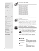
Safety Information FOR YOUR RECORDS System Model Numbers. . . . . . . 2 Write the model and serial numbers here: subtext For Your Records. . . . . . . . . . . . . 4 Model Number of Solar System Tank:______________________________ Introduction. . . . . . . . . . . . . . . . . 5 Serial Number of Solar System Tank:______________________________ Safety Precautions. . . . . . . . . . .
Introduction Thank you for purchasing a solar water heating system. It is one of the most effective and troublefree systems available today. In addition to reducing your water-heating bills, it will help preserve precious natural resources by using free energy from the sun. As with an electric or gas water heater, your new solar water heating system operates automatically to ensure you will always have an ample supply of hot water.
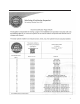
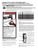
IMPORTANT SAFETY INFORMATION. READ ALL INSTRUCTIONS BEFORE USING. ! DANGER! WATER TEMPERATURE SETTING Safety and energy conservation are factors to be considered when selecting the water temperature setting of water heater’s thermostat. Water temperatures above 125°F can cause severe burns or death from scalding. Be sure to read and follow the warnings outlined on the label pictured below. BURN Water temperature over 125˚F can cause severe burns instantly or death from scalds.
IMPORTANT SAFETY INFORMATION. READ ALL INSTRUCTIONS BEFORE USING. WARNING! For your safety, the information in this manual must be followed to minimize the risk of fire or explosion, electric shock, or to prevent property damage, personal injury, or loss of life. Be sure to read and understand the entire Use and Care Manual before attempting to install or operate this water heater. It may save you time and cost. Pay particular attention to the Safety Instructions.
Installing the System Preface Let us first offer two words of grateful appreciation. Thank You! We sincerely appreciate your business. We also wish to say thank you for "going solar". Solar water heating systems help to reduce our nation’s dependence on polluting fossil fuels, minimize the greenhouse gas emissions associated with conventional water heating and, very importantly, lower your monthly utility costs.
Installing the System System Description and Operational Principle The key components in the solar water heating system include the solar collector, solar storage tank with integral heat exchanger, circulation pump, differential thermostat, expansion tank, pressure gauge, mixing valve and the non-toxic propylene glycol heat transfer fluid (HTF). The solar collector is the heart of the system.
Installation Requirements- General The contractor shall obtain all required permits and approvals. The installation shall conform to all federal, state and local regulations, codes, ordinances and standards governing solar water heating system installations, and the contractor shall adhere to sound building safety and trade practices. Special consideration must be given to building code requirements for the penetration of structural members and fire rated assemblies.
Installing the System Installation Requirements- Specific Collector Orientation The performance of solar water heating systems in the Northern Hemisphere is optimized when the collector is mounted facing True South. Performance, however, suffers very little when the collector is oriented no more than 45° East or West of True South. The collector should be unshaded by any permanent obstacle between 9:00 a.m. and 3:00 p.m. on any day of the year.
Basic Mounting Procedures The solar collector in your solar system can be mounted in either a vertical or horizontal orientation on the roof (See Figure 4). Although the collector is protected from freeze conditions by the glycol HTF and does not normally need to be drained, it is still important to slope the collectors just slightly to allow for complete drainage if necessary. The recommended slope is 1/4" per foot of horizontal run.
Installing the System FIGURES 5-10 Figure 5- Composition Shingle Mounting SOLAR COLLECTOR MOUNTING GROOVE SIDE VIEW SOLAR COLLECTOR MOUNTING CLIP 3/8" ST STL BOLT MOUNTING W/ LOCKWASHER & CLIP FLATWASHER ST STL SLIDING NUT ANODIZED ALUM SOLAR STRUT ST STL NUTS & WASHERS ROOFING SEALANT 12" X 12" LEAD FLASHING 3" MIN. ST STL HANGER BOLT SET IN SEALANT * LE NGTH & DIA. VARY WITH INSTALLATION * DR ILL PILOT HOLE 3/4 OF BOLT DIA.
FIGURES 5-10 SOLAR COLLECTOR SOLAR COLLECTOR MOUNTING CLIP MOUNTING MOUNTING GROOVE GROOVE MOUNTING CLIP - MOUNTING MOUNTING CLIP CLIP ST STL SLIDING NUT ST STL SLIDING NUT ANODIZED ALUM ANODIZED ALUM SOLAR STRUT SOLAR STRUT ST STL & WASH ERS ST STL NUTS &NUTS WASHERS ST STL HANGER BOLT ST STL HANGER BOLT SET IN SEALANT SET IN SEALANT * LENGTH & DIA. VARY * LE NGTH WITH & DIA. VARY INSTALLATION WITH * DRINSTALLAILL PILOT HOLE TION 3/4 OF BOLT DIA. * DR ILL PILOT HOLE 3/4 OF BOLT DIA.
Installing the System FIGURES 5-10 Figure 9 - Flush Mounting 15
FIGURES 5-10 Detail "D" Figure 10 - Universal Tilt Mount 16
Installing the System Installation Requirements- Specific continued Collector Loop Pipe Insulation The collector loop cold supply and hot return lines must be well insulated with a high quality flexible closed cell insulation to minimize heat loss. The wall thickness of the pipe insulation should not be less than 3/4". A 1" wall thickness is required in all areas prone to annual hard freeze conditions. When it comes to pipe insulation the rule is simple: thicker is better.
The sensor "bundle" must be placed under the rubber pipe insulation covering the collector header. Thoroughly wrap and weatherize the insulation with electrician’s tape or insulation tape as provided by the manufacturer (Rubatex InsulTape or equal). See Figure 13 for collector sensor installation detail. may require future service or maintenance make the connections with brass unions. Use only brass nipples and unions and copper and brass fittings in plumbing the solar storage tank and expansion tank.
Installing the System The circulation pump shall be the Grundfos model UPS15-5BFC/LC, 115 volt or equivalent. The pump shall be pre-wired with a 6’ line cord so that it can be plugged directly into the 115 volt receptacle on the side of the differential control. Isolation/Drain valves (No. 6 & 7) must be installed on either side of the circulating pump so that the pump can be isolated from the collector loop.
Proceed as follows: Charging the System WARNING: Under no circumstances can any fluid other than dowfrost hd be used, alternate fluids could be hazardous to your health. ! Once the components are plumbed you are ready to fill the solar storage tank with water and to charge the collector loop with a mixture of heat transfer fluid (HTF) and distilled or deionized water. The use of regular tap water as a mixing agent is prohibited. • Begin by filling the solar tank with water.
Installing the System • • Connect the discharge side of the pressure pump to the upper isolation/drain valve (No. 7) Place the pump suction side hose in the glycol solution. Close the isolation ball valve (No. 7) and connect a second hose to the lower isolation/drain valve (No. 6). Place the other end of the hose in the empty bucket. Open the upper drain valve and allow the pressure from the expansion tank to push the water in the glycol loop back to prime the pressure pump.
Operating the System System Start - Up Procedures Throughout the installation procedures outlined in Installation requirements - Specific, emphasis has been placed on the correct procedures for plumbing and wiring the components, checking for plumbing leaks, pressurizing the collector glycol loop, and eliminating any trapped air that can impact fluid quality and pump performance. Having completed these tasks it is time to start up your solar water heating system.
Operating the System Three Modes of System Operation Both single and double tank systems are designed to accommodate three separate modes of operation. Your solar water heating system can, (1) provide 100% solar operation during good weather, or (2) serve as a preheater to your electric or gas water heater adding solar energy when and as available, or (3) completely bypass the solar collector loop and solar storage tank and run 100% on utility power during inclement weather.
25 25 24 24 Figure 19a - 100% Solar Operation 25 Figure 19b - Solar Preheat Operation 24 Figure 19c - 100% Utility Power Operation Hot Outlet Cold Inlet See Handle Above 25 24 Figure 19d - Valve Position Diagram - Two Tank System 24
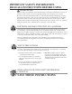
SOLPAK OG300 SYSTEM LABELS FLUID IDENTIFICATION: The heat transfer fluid used in this system is inhibited propylene glycol. It must be handled and disposed of in accordance with the manufacturers recommendations. BE EXTREMELY CAREFUL WHEN DRAINING THIS FLUID. IT MAY BE DISCHARGED AT A VERY HIGH TEMPERATURE AND PRESSURE. The heat transfer fluid used in the system shall be FDA generally recognized as sage (GRAS). No other fluid shall be used that would change the original classification of this system.
Use and Care of the System Isolating the Major Components and System Shut Down Procedures Your solar water heating system is designed so that the key components can be easily isolated for emergency repairs or routine maintenance. By shutting a single valve you can isolate the entire system from the pressurized cold water supply line (No. 19). In the case of a storage tank or fitting leak immediately shut this valve and call your installation contractor for service.
Maintenance and Troubleshooting The following simple procedures are intended to optimize the performance of your solar water heating system and also to extend the life of the primary components. • • • • • Fluid Quality: It is extremely important to monitor the quality of the Dowfrost HD HTF on a periodic basis. The chemical composition of the heat transfer fluid may change over time. System pH must be maintained between 8 and 10 to avoid damage to the collector loop and absorber plate piping.
Use and Care of the System Maintenance and Troubleshooting continued • You find a defective sensor replace it immediately. Note that in a two tank system nighttime heat loss will be harder to detect, especially if you are operating in the solar preheat mode. Check the line thermometers (No. 22) in the collector loop piping to detect night thermosiphoning.
Use and Care of the System 15) Cold Water Dip Tube: Forces incoming city cold water to the bottom of the solar storage tank to prevent mixing with the warm water at the top of the tank. (Provided) 16) Heat Exchanger: Transfers heat from the solar collector loop to the potable water in the solar storage tank. (Provided) 17) H eating Element & Tank Thermostat: The solar storage tank is equipped with an auxiliary 4500 watt, 230 volt electrical heating element.
System Schematics SINGLE TANK SYSTEM SCHEMATIC 2 Pipe Insulation Note: When two collectors are required, plumb in parallel.
DOUBLE TANK SYSTEM SCHEMATIC with Gas or Electric Back up Tank 2 Pipe Insulation 1 Collector Return Note: When two collectors are required, plumb in parallel.
System Schematics DOUBLE TANK SYSTEM SCHEMATIC with HEAT PUMP BACK UP TANK* 2 Pipe Insulation Note: When two collectors are required, plumb in parallel.
DOUBLE TANK SYSTEM SCHEMATIC with TANKLESS BACKUP 2 Pipe Insulation Note: When two collectors are required, plumb in parallel.
NOTES: 34
NOTES: 35
IF YOU NEED SERVICE 1. Should you have any questions about your new water heater, or if it requires adjustment, repair, or routine maintenance, it is suggested that you first contact your installer, plumbing contractor or previously agreed upon service agency. In the event the firm has moved, or is unavailable, refer to the telephone directory, commercial listings or local utility for qualified service assistance. 2.