
Use and Care Manual
Tankless Water Heater 3”/ 5” Concentric Direct Vent
Horizontal Vent Kit Installation Instructions
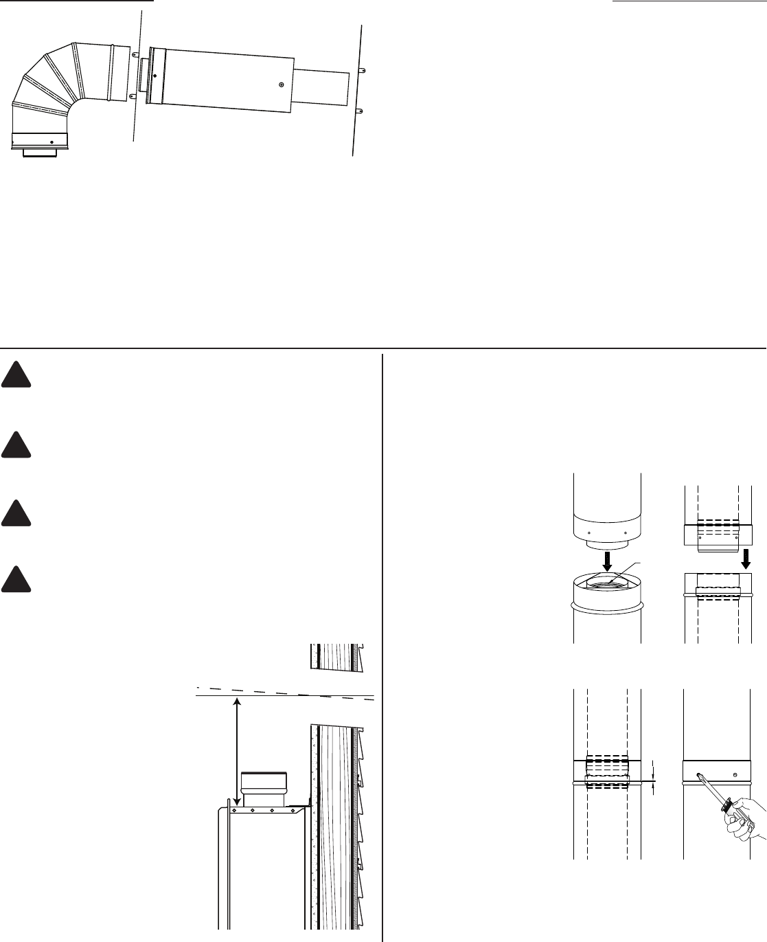
JOINT ASSEMBLY
Connections between vent and ttings are male/female type. The inner duct
is sealed with an integral seal gasket and the joint is mechanically secured
via the overlapping outer wall of the double wall pipe.
Joints are assembled per the
following steps:
A. Before assembly, observe
that the seal gasket is located
within the female inner pipe
joint. Locate next pipe or tting
with male inner pipe joint and
insert to begin engagement
of inner pipe joint. To help
the joints slide together apply
a light amount of silicone, or
water-based lubricant to the
silicone seals.
B. As the joint further
engages, align the male and
female ends of the outer wall of
each pipe so that they begin to
engage as the pipes are further
pushed together.
C. Pipe joint is fully engaged
when the female end of the
outer pipe comes in contact (or
is at least within 1/16
th
inch) to
the base of bead on the male
end of the adjoining vent pipe.
D. When possible look within
the pipe assembly to verify
that no sign of seal gasket is
showing. Complete the joint
assembly by securing the joint
using #8 x 1/2” sheet metal
screws (3 per joint) at each pre-
punched hole on the female
end of each joint.
Joint Assembly - Figure 2
SEAL
GASKET
A B
DC
1
16
" GAP (MAX.)
This instruction will only cover the installation of the Metal-Fab, Inc., Sealed Com-
bustion Horizontal Vent Kit to the tankless water heater. Refer to the Owner’s
Use and Care Manual provided with your Direct Vent Tankless Water Heater for
additional installation considerations and directions.
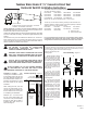
This kit contains:
94 degree elbow, Horizontal Termination, Trim Plates,
Hardware, and Installation Instructions.
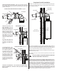
Installation Location – After
choosing the installation location
for the water heater, see the Use
and Care Manual provided with
the tankless water heater for in-
formation and clearances, mount
the water heater to the wall as
instructed.
When cutting the hole, cover the
vent of the water heater to pre-
vent any debris from falling into
the ue. Remove this cover prior
to completing the installation
Measure up 9 1/2 inches from
the top of the water heater and
cut a 6-inch hole (recommended)
through the wall, with a slight or
4-degree pitch down to the out-
side. See Figure 1.
9 1/2 Inches
6-Inch Hole
Recommended
TANKLESS
WATER
HEATER
Location Opening - Figure 1
1
AP15596-1
L2614
RTG-95DVN RUTG-95DVN RMTG95DVN ECO200DVN3
RTG-84DVN RUTG-84DVN RMTG84DVN ECO180DVN3
RTG-64DVN RUTG-64DVN RMTG64DVN ECO150DVN3
PH2-28RDVSN PH2-25RDVSN PH2-20RDVSN
Replace the “N” sufx for Natural Gas with a “P” for LP Gas
This kit may be used with the following models provided a RTG20144-3
Appliance Adapter is installed, must be purchased separately. Installation
distances will vary from the instruction below.
RTG-66DV* RTG-53DV* PH-25R DVS* ECO-180DV*
RUTG-66DV* RUTG-53DV* PH-20R DVS* PTG-53DV*
RMTG-66DV* RMTG-53DV*
* P - sufx for LP Gas
* N - sufx for Natural Gas
The Sealed Combustion Horizontal Vent Kit (RTG20210) is designed for use
with ONLY the following models:
It is very important that all persons who are expected to install, operate,
or adjust this vent system and/or water heater read these instructions
along with those instructions provided with the tankless water heater.
DO NOT ATTEMPT TO CUT THIS VENTING MATERIAL.
CUT SECTIONS WILL NOT SEAL AND COULD CAUSE
IMPROPER OPERATION OF THE WATER HEATER.
Unpack the Horizontal Vent Kit, inspect all parts for damage, and make
sure none of the parts are missing. Contact the supplier if there are parts
missing.
!
!
!
!
WARNING: SHEET METAL SCREWS ARE FOR OUTER
WALL ONLY. NEVER USE SCREWS, RIVETS OR OTHER
FASTENERS TO PENETRATE THE INNER PIPE WALL.
WARNING : IMPROPER INSTALLATION OF VENTING,
OR FAILURE TO FOLLOW ALL INSTALLATION
INSTRUCTIONS COMPLETELY, CAN RESULT IN
PROPERTY DAMAGE AND/OR DEATH.
NOTICE: THIS KIT CONTAINS SHEET METAL PARTS,
WHICH MAY HAVE VERY SHARP EDGES. USE LEATH-
ER GLOVES WHEN HANDLING VENT COMPONENTS.
NOTICE: Additional vent piping can be purchased separately to extend
the installation of this kit.
See the Use and Care Manual provided with the
tankless water heater for maximum vent lengths.
4-degree
downward pitch