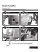
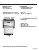
Steam Humidifier As Easy as 1-2-3-4 PROFESSIONAL INSTALLATION GUIDE 1 Mount 2 Hang 3 Plumb 4 Wire See inside for detailed instruction and remote mounting options! 69-2307-01
Installation Guide Table of Contents Installation Recommendations....................................................... 1 List of tools/supplies....................................................................... 2 Safety Precautions.......................................................................... 3 Duct Mount Instructions Installation........................................................................................ 4 Remote Mount Instructions Installation..............................
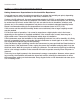
Humidification System Installation Recommendations Make your installation accurate and efficient by addressing these commonly asked questions: Sizing for the Job 1. Selecting the appropriate humidifier for the job is critical: The table below illustrates the square footage the humidifier can serve. It is not recommended to install a 6 gallon device in a home larger than 2000 square feet. Square Feet of Space 500 1000 1500 2000 2500 3000 ARI* Recommended Output Delivery (GPD) 0.1 2.2 4.4 6.5 8.
Installation Guide Installation Recommendations Setting Homeowner Expectations for the humidifier Experience: It may take up to a week of continuous operation to achieve the humidity set point, depending on weather, size of home, furnishings in the home, insulation, etc. If using a six (6) gallon unit, the most appropriate setpoint is 30-35% or until there is condensation on the windows, then lower the setpoint.
Humidification System What you will need to install the Humidistat Tools/Hardware needed: Material Provided: • Wire stripper/cutter • 1/4-in. copper or plastic water line • Drill or duct-cutting tool • 1/2-in. drain hose and clamps • 1-3/4-in. hole saw • Mounting bracket and hardware • 1/8-in.
Installation Guide Safety Precautions CAUTION: Voltage Hazard. Can cause electrical shock or equipment damage. Disconnect HVAC equipment before beginning installation. Safety Precautions • Do not direct the steam nozzle at people. • If used near a pool or spa, ensure the humidifier can not fall into the water or be splashed. Also, ensure the humidifier is plugged into a GFI ground fault interrupt outlet. • Water inside tank can be very hot.
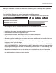
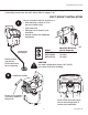
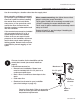
Humidification System If installing the humidifier directly to the supply duct, follow steps on pages 5–6 and 14–18. If mounting remote from the duct, follow steps on pages 7–18. DUCT mount installation 1 Choose a location that has access to a: • Drain allowing a slope of 1/4 in. per foot of drain hose. • Cold water line. • Electrical circuit rated to your humidifier. • Vertical surface with adequate clearances. Model RXIH-AS06A RXIH-AS09A RXIH-AS12A Continuous downslope Draining water may be hot.
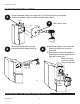
Installation Guide DUCT mount installation 3 Position template sticker on supply duct. For tall coils that do not have this clearance available, refer to remote mounting instructions. SUPPLY 4 Drill 1-3/4-in. hole. 12 INCHES M24748 5 Secure bracket to duct using #8 self-drilling sheet metal screws (4). 6 A) Slide foam gasket over nozzle and insert the nozzle into duct hole (pictured). B) Push down to secure humidifier to bracket arms. Ensure gasket forms tight seal in duct hole. Allow 3 in.
Humidification System Remote mount installation Use for mounting to a location other than the supply duct. Most operation problems are caused by improper hose installation. Always ensure an uphill flow when installing the remote hose, and avoid kinks, sharp turns, or low spots that could restrict the flow of steam into the injection nozzle or condensation back into the humidifier. If the remote hose cannot be installed with an upward pitch of 2 in./ft., a wetted drip tee must be installed.
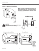
Installation Guide Proper Hose Installs Furnace or Mechanical Room Remote Note: If air handler location temperatures will drop below freezing at any time, the humidifier must be mounted in a conditioned space, running a remote hose to the duct. Duct Mount Remote M24781 CAUTION Hot water temperature above 120°F (49°C) can cause burns from scalding. M24936 Garage Remote Living Area Remote Options M24786 M24785 69-2307—01 8 Draining water may be hot. Ensure drain outlet not exposed.
Humidification System PRoPeR hose InsTalls 20 FT MAX WITH TRAP 2 IN. PER FT 5 FT MAX IF NO SLOPE 3 FT MAXIMUM P - TRAP DRAIN TYPICAL INSTALLATION WHEN HUMIDIFIER IS ABOVE REMOTE NOZZLE 20 FT MAX 10 FT MAX GENTLE BEND 2 IN. PER FT DRAIN P - TRAP 2 IN. PER FT 2 IN. PER FT OBSTRUCTION SUPPORTED REMOTE HOSE WETTED P - TRAP NOTE: HEIGHT OF TRAP MUST BE GREATER THAN THE DUCT STATIC PRESSURE DRAIN NOTES: • Minimum upward slope of hose in direction of steam flow at 2 in.
Installation Guide Remote mount installation Model RXIH-AS06A RXIH-AS09A RXIH-AS12A Minimum Circuit Capacity 7 Amps 10 Amps 12 Amps M24745 2 Draining water may be hot. Ensure drain outlet not exposed. Install hose adapter from Remote Mount Kit. Ensure o-ring gasket is properly seated in the groove. Continuous downflow M24744 CAUTION Hot water temperature above 120°F (49°C) can cause burns from scalding.
Humidification System Remote mount installation Position template sticker on remote location. Note: The humidifier will weigh 12–15 lbs. (+/- 2 lbs.) with water, so if mounting onto drywall or plaster, position one side over a wall stud. 3 M24766 4 Insert wall anchors (4) into pilot holes and secure bracket to location. 5 M24767A Push down to secure the humidifier to bracket arms.
Installation Guide Remote mount installation 6 Cut a 1-3/4 in. diameter duct hole, install the provided gasket, and slide the remote nozzle up into the duct. Secure remote nozzle to duct using #8 self-drilling sheet metal screws (4). 7 Run remote hose from the humidifier to the duct nozzle location. Up to 20 ft. of hose can be used. Minimum 3 in. clearance required from nozzle outlet to duct wall. M24770 If mounting remotely requires running hose through structural barriers (ie.
Humidification System Remote mount installation To install clamps onto the insulated steam hose: A Cut a slit in the insulation half way around the house. Do not cut into the steam hose. B Insert the hose clamp into the slit and hook it onto the hose.
Installation Guide Plumbing A Insert 1/4-in. water line into filter. Apply modest pressure to ensure a tight fit. B Insert 1/4-in. water line into back-flow valve. Apply modest pressure for a tight fit. C Connect 1/2-in. drain tube. Secure drain tube to barbed fitting with hose clamp. D Shut off the water supply. Secure 1/4-in. copper or plastic water feed tube.
Humidification System wiring 11 Loosen captive cover screw. Slide cover out from front. CAUTION: Voltage Hazard. Before wiring to HVAC terminals, disconnect HVAC equipment power. Ensure humidifier is not plugged in. M24754 Low-Voltage Terminals 24V 24V HUM HUM C GT R RT GF EXT 24V AC power for electronic humidistat. HUM Low-voltage humidistat (or thermostat) terminals control humidifier operation.
Installation Guide wiring Wire the humidifier according to the diagram that applies to your humidity control. 12 Follow this diagram if using a mechanical humidistat. Follow this diagram to wire Automatic Digital Humidistat for manual operation. MECHANICAL HUMIDISTAT HVAC Set the digital humidistat ISU parameter 10 to 1, and ISU 25 to 2. For auto-operation: also wire W and G to thermostat B DIGITAL HUMIDISTAT W and G.
Humidification System Wiring 13 Slide the cover back into place and secure captive screw. Turn on the water supply and plug in the humidifier. POWER HUMIDIFYING CLEAN TANK SEE LABEL BELOW ! 14 CALL SERVICE PRESS RESET The Press Reset light will blink when power is applied. Press/release the RESET button to ready the humidifier. If not pushed, the humidifier will automatically move to ready after five minutes.
Installation Guide dIP sWITCH sELECTION Between the transformer and LED display on the circuit board are two sets of DIP switches. DIP 1 and 2 can be configured to adjust cleaning cycles. DIP 4 and 5 can simplify wiring. DIP 3 and 6 are not used at this time. Details below. Run time (hrs) DIP 6 DIP 5 DIP 4 DIP 3 DIP 2 DIP 1 ON End-of-Season timer (hrs) 10 hrs of humidify- 48 hrs before system autoing before system drains and remains empty auto-flushes debris until next call for humidity. from tank.
Humidification System Troubleshooting The humidifier has internal system diagnostics that monitor system operation, maintenance schedules, and faults. If a system fault is detected, the system will attempt to recover itself up to five times in a 24 hour period. If unable to recover in that time, the red Call Service LED light will activate. If the humidifier Call Service light is red, a system fault has occurred from which the humidifier can not recover by itself.
Installation Guide Troubleshooting No. of Red Light Blinks 4 Fault Description AutoRecoverable? Heating element overheated. No 5 Input voltage insufficient. 6 Water overflow sensed. Steps to Fix To be Performed by Professional HVAC Technician Only • • • Yes, system will • return to “Ready” • if fault no longer • exists in 1 hour. • Yes, system will • return to “Ready” if fault no longer • exists in 1 hour.
Humidification System Troubleshooting No. of Red Light Blinks 8–11 12 Fault Description AutoRecoverable? The backup weld monitor input is active when the backup heater relay is off. Temperature of the electronic circuit board is too high. No Steps to Fix To be Performed by Professional HVAC Technician Only • Replace the unit. Yes, system will • return to “Ready” if fault no longer exists in 1 hour. • • • • • 13 • • • • Tank failed to drain. No 14 Heater failed to boil water. 15 No Airflow.
Installation Guide Specifications Capacity: RXIH-AS12A: 12 gallons per day (gpd) (45 liters per day [lpd]) RXIH-AS09A: 9 gpd (34 lpd) RXIH-AS06A: 6 gpd (23 lpd) Electrical Ratings and Tolerances Input Ratings • Power Supply: 120VAC +10/ -15%, 60Hz - RXIH-AS12A: 1440W at 120VAC at full load - RXIH-AS09A: 1200W at 120VAC at full load - RXIH-AS06A: 840W at 120VAC at full load • RXIH-AS12A: 12A, 120VAC • RXIH-AS09A: 10A, 120VAC • RXIH-AS06A: 7A, 120VAC • 15A, 120VAC interlock switch • Thermostat/HVAC power mo
Humidification System Cleaning and Seasonal or Vacation Maintenance Maintenance is simple with the humidistat—just remove the water tank for cleaning. Warning: Scalding hazard. Do not attempt to remove the humidifier from the mounting bracket during operation, or when the humidifier’s water tank when full of water. Water heater could be hot when tank is removed. Failure to comply could result in severe scalding or death.
Installation Guide Cleaning and Seasonal or Vacation Maintenance 3. Grip the white water valve arm and slide it back within the bracket to disengage from the tank. 2. Turn the manual shut-off valve at the bottom of the tank to the “Unlock” position. M24777 M24779 4. Firmly grip the tank bottom. Push down the cover's safety button and pull the latch forward to release the tank. Note: Latch does not come off humidifier with tank. 5. Use tap water to flush loose minerals from the tank.
Humidification System Cleaning and Seasonal or Vacation Maintenance 7. Replace inline filter once per year. Turn water supply off before replacing. Press down filter collar ring and pull out 1/4 in. water line from each side. Insert 1/4 in. lines into new filter. Apply modest pressure to ensure a tight fit. M27410 M27411 Once clean, reattach tank by securing the latch. Engage the water valve to the cam shaft, and “Lock” the shut-off valve. The “Press Reset” light will blink at start-up.
Parts List Part 10-foot Remote Hose and Nozzle Kit 20-foot Remote Hose and Nozzle Kit Duct Nozzle Remote Nozzles Mounting Bracket Solenoid Valve In-Line Water Filter RXIH-AS12A/RXIH-AS09A Water Tank RXIH-AS06A Water Tank Water Level Sensor Assembly Saddle Valve Back-flow Water Valve Differential Pressure Switch Part Number 50024917-001 50024917-002 50028003-001 50028001-001 50020012-001 50027997-001 50028044-001 50033181-001 50033182-001 50027998-001 32001616-001 50030142-001 50027910-001 Fig.