SERVICE INSTRUCTIONS Premier Loline Solar Drain Back Water Heater TM024 Revision: A Published: December 07 590270 591270 596270 This document is stored and maintained electronically by Service.
Contents Safety Warning .................................................................................................................... 3 Introduction .......................................................................................................................... 3 Water Heater Model Identification ........................................................................................ 3 Specifications............................................................................................
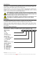
Safety Warning The purpose of this service manual is to provide sufficient information to allow a person with the skills as required by the Regulatory Authorities to carry out effective repairs to a Rheem Premier Loline Water Heater in the minimum of time. Safety precautions or areas where extra care should be observed when conducting tests outlined in this service manual are indicated by print in bold italics and/or a warning symbol. Take care to observe the recommended procedure.
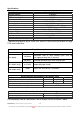
Specifications Specification Storage capacity Temperature setting TPR valve setting Solar circuit relief valve Max supply pressure Min supply pressure Water connections- tank Water connections- collector Collector(s) type Supply voltage Solar circuit fluid Anodes Solar circuit pump Solar circuit aux pump (optional) 590, 591 & 596 Models 270 Litres 60ºC 1000kPa 200kPa 800kPa (680kPa with ECV) 200kPa Inlet RP¾/20, Outlet RP¾ /20 Hot pipe ½” BSP, Cold pipe ½” BSP S200 or T200 220 – 250 Volts AC 50Hz *4.
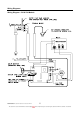
Wiring Diagrams Wiring Diagram - 590 & 596 Models TM024 Premier Loline Solar Drain back Service Instructions REV: A D.O.I: 12/12/2007 This document is stored and maintained electronically by 5 Service.
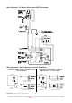
Wiring Diagram - 591 Models (Robertshaw EWT Thermostat) Wiring Diagrams - Electric Booster Circuit All 591 Models Continuous power supply to booster circuit - All 591 Models Extended Off-Peak power supply to booster circuit - All 591 Models Switchboard Switchboard Extended Off-Peak Power Supply (no manual switch or timer) Continuous Power Supply (no manual switch or timer) Continuous Power Supply Continuous Power Supply (with manual switch or timer) TM024 Premier Loline Solar Drain back Service Instr
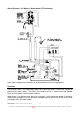
Wiring Diagram - 591 Models (Robertshaw ST Thermostat) Note: Refer to page 6 for continuous or off-peak booster circuit wiring diagrams. Operation The Premier Loline is an indirect drain back solar Loline (collectors at roof level, cylinder at ground level) water heater. The fluid in the collector circuit is isolated from the potable water in the cylinder, hence the term ‘indirect’.
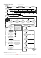
Operational Flow Chart Operational Flow Chart Plug In Power On Restore Power Rectify fault Pump relay de-energised (if on) Isolate Power (1) Self check routine normal? NO Software malfunction YES Pump relay energised Hot sensor open circuit Hot sensor short circuit Cold sensor open or short circuit Thermistors open or short circuit Sensor strip unplugged Red LED 1 flash Red LED 2 flash Red LED 3 flash Red LED 4 flash Red LED 5 flash (2) Is tank temperature > or = 75ºC? Green LED 5 flash
Sequence of Operation - Solar The following sequence of operation is common to 590, 591 & 596 models and pertains to the solar circuit which is a ‘closed circuit’ containing a heating fluid consisting of propylene glycol and water. For information on electric and gas booster operation refer to page 10. Refer to ‘Sequence of Operation Component Diagram’ on page 10 to view components shown in brackets e.g. (1). 1. When power is supplied to the appliance the controller (1) performs a self check routine.
9. Once the pump (6) ceases operation the system commences to drain back. Fluid in the collectors (8) begins to fall back to the bottom of the heat exchanger (9) via the cold pipe (10) due to gravity; this creates suction on the fluid in the hot pipe (12) which is also drawn back through the collectors (8). At the same time the heated vapour in the heat exchanger (9) is rising up through the distributor (11) and into the hot pipe (12) also forcing the fluid back through the collectors (8).
Gas Boosted Integrated Plumbing Arrangement Solar Circuit It is imperative that both the collector hot and cold pipes must fall continuously by at least 5º, or a 1 in 10 fall, to ensure proper drain back of heat exchange fluid into the storage cylinder. Each collector should be angled 10-15mm from horizontal towards the hot outlet to ensure proper drain back of heat exchange fluid and to ensure that the hot sensor is located in fluid when the pump is on.
Solar Circuit Plumbing Diagrams - All Models The solar collectors must be the highest point of the system. The maximum height of the solar installation, from the base of the solar storage tank to the top of the solar collectors, is 9 m. The pump supplied will not circulate closed circuit fluid through heights greater than 9 m and solar gain will not be achieved. For heights greater than 9m, an auxiliary pump kit (PN 299914) must be installed.
Auxiliary Pump - Solar Circuit The maximum height of the solar installation from the base of the solar storage tank to the top of the solar collectors is 9 m. The pump supplied with the solar storage tank will not circulate closed circuit fluid through heights greater than 9 m and solar gain will not be achieved. For heights greater than 9 m, an auxiliary pump kit (kit PN 299914) must be installed above and within 1 m of the solar storage tank.
Potable Water Plumbing Diagrams Plumbing Diagram - 590 & 591 Models Two temperature zones utilising temperature limiting device Plumbing Diagram - 596 Models Two temperature zones utilising temperature limiting device integrated with water heater Gas boosted integrated plumbing behind front access cover contains a tempering valve and provides both a hot (75ºC) and tempered (50ºC) water outlet. Note: Refer to page 11 for gas boosted integrated plumbing arrangement.
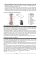
Electronic Controller The control board or electronic controller is used to control the pump by monitoring the water temperatures and heat transfer temperatures at various locations within the system. By monitoring the temperature of the heat transfer fluid returning to the solar collectors (cold sensor) and the temperature of the fluid at the outlet of the collectors (hot sensor), the controller adjusts the pump speed to regulate the temperature rise through the collectors to 10ºC.
Solar Monitor Plug Polarity Test 1. Release water from the T&PR valve until the water temp in the cylinder is < 75ºC. 2. Switch off power for 5 seconds and then restore power. 3. If the LED flashes green (any combination) or is solid red within the first 15 seconds from restoring power, the solar monitor plug is inserted the wrong way around. Solar Monitor LED Indication Each flash lasts for 0.5 seconds and each series of flashes is separated by a two second interval.
Pump An electro-mechanical device that pumps solar transfer fluid through the collectors by centrifugal force. The control board varies the flow rate of the pump by pulsing the electrical supply to the pump motor. The flow rate is proportionate to the pulse rate. e.g. higher pulse rate = higher flow rate. Pump Relay The pump is controlled and switched by the control board however the pump power supply may be interrupted by the relay in the event of a software malfunction or over temperature condition.
Heating Unit (Element) - 591 Models Only A tubular device containing an electric resistance element that converts electrical energy to heat. Standard element ratings are 2.4kW, 3.6kW and 4.8kW. Integral Gas Booster - 596 Models Only An Integrity 26 litre electronic gas instantaneous water heater mounted externally on the heater jacket which will boost the solar preheated water to 60ºC if required. Refer to page 10 for more information.
Effective 10/08/07 – Solar Cold Connection • • • The cold pipe which is foamed into the heater had the large brass fitting removed so that just the pipe protrudes. Item 2 – Union ½”C x ½”M is replaced by 088065 compression union ½”C x ½”C which is now item 2a. Item 10 - 087035 Rubber disc is replaced by 221754 Kelvindale plug which is now item 10a. Note: This means the solar cold connection is different although the installing plumber still makes to two ½” copper connections.
Common Faults When a complaint is lodged about the performance of a hot water system there are a number of causes that should be checked and eliminated. In an attempt to pinpoint the most likely cause it is important to discuss with the customer their reasons for the complaint, the duration of the problem, any change in circumstances or usage and recent weather conditions. This information in conjunction with the following listed common complaints will assist you in locating the most likely cause.
Roof leaking This complaint is usually made during or after wet weather and normally soon after commissioning a new water heater. The movement of persons on the roof during installation can crack roofing material if the load is borne on specific points or the roof material is brittle. \ Replacement of damaged roof materials is essential. Use of a woven plastic roof sheet below the collectors will make water penetration more difficult in the future.
Testing the Sensor Strip Unplug the sensor strip plug from the control board and using a multimeter on the kiloohms scale, measure between the pins of the sensor strip plug*. There are six individual tests to be performed as there are six individual sensors contained along the length of the sensor strip (sensors S0 – S5).
Testing the Hot and Cold Sensors Unplug the relevant sensor from the control board and remove the sensor from its location so its temperature will be the same as the ambient air temperature. Using a multimeter on the kilo-ohms scale, measure between the two pins of the sensor plug*.
Fault Diagnosis Sequence (General Fault Finding Chart) General Fault Finding Chart Fault 591 (electric boosted) Is the complaint for no hot water? What is the model number? YES 1 596 (gas boosted) 1.1 590 (solar pre-heater) 1.2 NO Is the complaint for insufficient hot water? 2 YES NO 591 (electric boosted) Is the complaint for water too hot? What is the model number? YES 3 596 (gas boosted) 1.1 590 (solar pre-heater) 3.
Fault Finding Chart 1 1 Is the electric booster connected to an off peak tariff? Test 1 Is 240 volts present at the terminal block? NO NO YES Possible failure of the off peak relay or missed signal from energy supplier Continue diagnosis to confirm booster circuit is operational. YES Is a switch to control the booster installed in the house? NO Isolate power and continue with diagnosis procedure.
Fault Finding Chart 1.1 1.1 Is the water temp in the tank < or = 58º? No or Insufficient Hot Water YES Water Too Hot Is the gas booster operating? NO The tank water temperature can be determined by gently lifting the easing lever on the T&PR valve and measuring the water temperature at the discharge Is the gas booster operating? NO Conduct fault finding on the gas booster. Refer to appropriate Service Instructions for model. YES Test 2 Is 240 volts present at the terminal block? 3.
Fault Finding Chart 1.2 1.2 Is a tempering valve blocked or faulty? YES Replace tempering valve. NO Is an in-line booster plumbed in series? NO 590 models require an in-line booster otherwise no hot water will be available in periods of low solar gain. Advise customer and continue with diagnosis to ensure solar system is operational. YES Conduct fault finding on the gas booster. Refer to appropriate service instructions for model. Repair gas booster before progressing past this point.
Fault Finding Chart 1.3 1.3 Test 3A for EWT type thermostats or test 3B for ST type Are thermostats the thermostat ECO contacts closed? Reset the ECO or replace thermostat.
Fault Finding Tests 3A – 4B Test 3A – EWT Type Thermostat Test 3B – ST Type Thermostat Warning - Ensure power is isolated before conducting this test. Warning - Ensure power is isolated before conducting this test. Using a multimeter on the ohms scale, measure between the terminals of the mechanical thermostat. The following results should be obtained: Using a multimeter on the ohms scale, measure between the terminals of the mechanical thermostat.
Fault Finding Chart 1.4 Electrical Insulation Test 1.4 Disconnect wiring to electric booster at the terminal block and megger between each wire to the electric booster and earth. 591 (electric boosted) What is the model number? 596 (gas boosted) 590 (solar pre-heater) Is the reading below 1 mega-ohm? NO YES Disconnect the element wiring from the thermostat and megger between each element wire and earth. Is the reading below 1 mega-ohm? YES Replace element.
Fault Finding Chart 1.5 1.5 Is 240 Test 2 volts present at the terminal block? YES Is the fuse blown at the switchboard? NO Reinsert solar monitor plug firmly into control board socket. Does solar monitor provide any indication? NO YES Is the solar monitor plug inserted correctly? NO NO Replace solar monitor. (1) Is the solar monitor plug inserted with correct polarity? Unplug solar monitor from control board and reinsert plug after rotating 180º. NO 1 flash Hot sensor open circuit. 1.
Fault Finding Chart 1.6 1.6 (1) (2) Does the pump(s) operate? Pump operation can be checked by feeling the pump body for vibration NO Is there 6VDC at the relay coil? Notes (1) For collector heights between 9 & 18 metres an auxiliary pump (pump 2) must be installed and included in these tests. For heights < 9 metres pump 2 is not required. (2) If the green LED is indicating 4 flashes, pump 2 will be off and will not operate.
Fault Finding Tests 5 – 7B Test 5 Test 6 Warning - Ensure power is isolated before conducting this test. Warning – ‘Live’ equipment wear Personal Protective Equipment when conducting this test. Disconnect the element wires from the thermostat, and using a multimeter on the ohms scale, measure between the two element wires. The following results should be obtained: Using a multimeter on the DC voltage scale, measure between the two wires on the control board relay plug. Normal voltage is 6 Volts DC. 2.
Fault Finding Tests 8 – 9B Test 8 Warning – ‘Live’ equipment wear Personal Protective Equipment when conducting this test. Using a multimeter on the AC voltage scale, measure between the N/O terminal of the pump relay and neutral on the control board power supply plug. Normal reading is 240 Volts. Test 9A – Pump 1 Test 9B – Pump 2 Warning - Ensure power is isolated before conducting this test. Warning - Ensure power is isolated before conducting this test.
Fault Finding Chart 1.7 1.7 Is the collector height between 9 & 18 metres high? YES NO Is an auxiliary pump installed? NO Install an auxiliary pump. YES Is the collector height > 18 metres? YES Max allowable collector height is 18 metres. System will not operate correctly at heights > 18 metres. YES Reduce solar pipe work length and/or number of bends. NO Remake pipe work and/or bends/fittings so as correct fall is provided. Adjust collectors to provide correct fall.
Fault Finding Chart 1.8 1.8 Is the collector glass broken or dirty? Clean the collector glass or replace the collector. YES NO Is the coating on the collector absorber plate deteriorating? YES Is the daily water usage exceeding the solar heating capacity? No hot water NO Is the daily water usage exceeding the solar heating capacity? What was the original complaint for? YES Replace the collector.
Fault Finding Chart 2 & 2.1 2 Is the water heater of sufficient size for the customers needs? Has the usage pattern changed recently? i.e. additional appliances or people using hot water NO YES 2.
Fault Finding Chart 3, 3.1, 3.2 & 3.3 3 Is the water temperature at a hot tap 60 - 75º? Is a tempering valve fitted? YES Test 3A for EWT type thermostats or test 3B for ST type Are thermostats the thermostat NO ECO contacts ECO has tripped closed? YES NO Replace the tempering valve. Advise customer on operation of Premier Loline system and benefits of storing water at 60 - 75º. Tempering valves should be considered for ablution areas if concerns surround small children or elderly occupants.
Fault Finding Chart 4 4 Notes (1) The T&PR may under normal operating conditions discharge up to 10 litres over a 24 hour period; therefore a small discharge may occur whilst appliance is heating – Normal operation. Is boosting required during periods of high solar gain to meet hot water demands? NO 1.5 YES Are there any leaks around the collectors or heater? Is the leak discharge from the T&PR valve? YES YES NO 5 NO (1) Is the T&PR valve continuously discharging water? YES 2.
Fault Finding Chart 5 5 Is the leak from the tank? YES Is the leak discharge from the T&PR valve? (1) Is the T&PR valve continuously discharging water? YES NO Is the leak from the anode? NO NO If fitted Is the leak from the element gasket? NO YES Reseal the anode. Notes (1) The T&PR may under normal operating conditions discharge up to 10 litres over a 24 hour period; therefore a small discharge may occur whilst appliance is heating – Normal operation.
Fault Finding Chart 6 6 Is the noise only evident when the electric heating cycle is on? YES Is there mineral build up on the heating unit? YES Poor quality water supply i.e. dam water sludge. Flush Tank. NO Is the noise water hammer? NO Replace heating unit. Refer to water hammer causes in the ‘Common Complaints’ section. YES NO Is the noise only evident when water is flowing through the water heater? YES Check all other appliances that can generate noise i.e.
Voltages up to 240 volts will be present within the water heater, take care not to touch wiring terminals. Use an insulated tool when operating the DIP switch or MIN and MAX buttons. 1. Remove the front cover from the water heater. 2. Turn DIP SWITCHES 3 and 4 on (up position) on the I.C. Board. The current preset temperature is displayed on the LED. 3. Press the MIN or MAX button, located under the DIP Switches, until 60ºC is displayed. 4. Turn DIP SWITCHES 3 and 4 off (down position).
591 Models Procedure 1: Insulation resistance of the water heater Neutral Circuit. (Reading not to be below 0.66 Mega ohm). 1. Isolate power to the water heater by removing fuse(s) or switching off circuit breaker(s). Confirm with multi-meter across terminal block Active A1 and Neutral, then Active A1 and Earth, then Neutral and Earth that voltage is not present. 2. Confirm with multi-meter across terminal block Active A2 and Neutral, then Active A2 and Earth that voltage is not present. 3.
Component Replacement Procedures Draining the Water Heater (Procedure 1) Elevated temperatures may be present during the draining process. Wear Personal Protective Equipment to prevent scalds or burns. Wear Personal Protective Equipment when conducting step 3 of this procedure to reduce the risk of electric shock. Refer to Rheem Safety Procedure on electrical testing. 1. Isolate power and water supplies to the water heater. 2. Relieve pressure from the water heater through the T&PR valve or a hot tap. 3.
Temperature and Pressure Relief Valve (Procedure 3) Never fit a T&PR valve with a rating higher than that indicated on the water heater rating plate. Do not use reconditioned T&PR valves. 1. 2. 3. 4. Isolate power and water supplies to the water heater. Relieve pressure from the water heater through the T&PR valve or a hot tap. Remove the drain line from the T&PR valve. Unscrew the T&PR valve and remove. A quantity of hot water will discharge from the tank during this process.
Anodes (Procedure 7) Elevated temperatures may be present during anode removal process. Wear Personal Protective Equipment to prevent scalds or burns. 1. Isolate the power and water supplies to the water heater. 2. Relieve pressure from the water heater and drain approximately 10 litres of water from the cylinder through the T&PR valve. 3. Remove the anode cap(s). 4. Using a 27mm tube or socket spanner remove the anode(s). 5. Apply thread seal tape to replacement anode, refit and tighten.
Pump Relay (Procedure 10) Wear Personal Protective Equipment when conducting step 2 of this procedure to reduce the risk of electric shock. Refer to Rheem Safety Procedure on electrical testing. 1. Isolate power supply to the water heater and remove pump access panel (refer to procedure 4). 2.
Hot Sensor (Procedure 13) 1. Isolate power supply to the water heater. 2. Remove the spring clip retaining the hot sensor in the collector connector and remove the locating washer and hot sensor. 3. Fit the replacement sensor into the connector and secure with the spring clip. Ensure the clip retains the locating washer. 4. Cut the wiring to the existing sensor and connect to the replacement sensor. Ideally this connection should be made in the roof space.
Pump Isolation Valve (Procedure 16) Ensure any escaping solar circuit fluid is contained and does not enter any part of a rainwater tank system as entry will render the water undrinkable. 1. Remove the solar circuit relief valve by following steps 1 – 6 in procedure 2. This will relieve the solar circuit pressure. Note: ensure all warnings in procedure 2 are observed and adhered to. 2. Attach one end of a ½” flexible hose to heat exchanger drain valve and insert the other end into a clean container. 3.
Gas Booster – 596 Models Only (Procedure 19) A quantity of hot water may discharge from the gas booster and tank and gas booster hot pipes during this procedure. Wear Personal Protective Equipment to prevent scalds or burns. Wear Personal Protective Equipment when conducting step 3 of this procedure to reduce the risk of electric shock. Refer to Rheem Safety Procedure on electrical testing. 1. Isolate power, gas and water supplies to the water heater. 2.
Heating Unit – 591 Models Only (Procedure 21) Wear Personal Protective Equipment when conducting step 1 of this procedure to reduce the risk of electric shock. Refer to Rheem Safety Procedure on electrical testing. 1. Drain the water heater. Refer to procedure 1. 2. Remove the upper electrical access cover (refer to procedure 5) and disconnect the wiring from the terminal block. Disconnect the wiring to the heating unit from the thermostat.
Exploded View 1 – 590 & 596 Models TM024 Premier Loline Solar Drain back Service Instructions REV: A D.O.I: 12/12/2007 This document is stored and maintained electronically by 52 Service.
Replacement Parts List (Exploded View 1) Item 1 2 2a 3 4 5 6 7 8 9 10 10a 11 12 13 14 15 16 17 18 19 20 21 22 23 24 25 26 27 28 29 Description Closed Circuit Relief Valve 200kPa Union ½”C x ½”M (pre 19/9/06) Compression Nut 1/2” Anode Cover Jacket Top Extension Fitting – Relief Valve Pipe Seal – Solar Conn/Solar Relief valve Foam Cover Hand Grip Spring Clip - Relief Valve Rubber Disc – Transport item only Kelvindale Plug – Transport item only Compression Olive Extension Fitting – Solar Hot Connection O-rin
Exploded View 2 – 591 Models TM024 Premier Loline Solar Drain back Service Instructions REV: A D.O.I: 12/12/2007 This document is stored and maintained electronically by 54 Service.
Replacement Parts List (Exploded View 2) Item 1 2 2a 3 4 5 6 7 8 9 10 10a 11 12 13 14 15 16 17 18 19 20 21 22 23 24 25 26 27 28 29 30 31 32 33 34 35 36 37 38 39 40 41 42 43 44 45 46 47 Description Closed Circuit Relief Valve 200kPa Union ½”C x ½”M (pre 19/9/06) Compression Nut ½” Anode Cover Jacket Top Extension Fitting – Relief Valve Pipe Seal – Solar Connections Foam Cover Hand Grip Spring Clip - Relief Valve Rubber Disc – Transport item only Kelvindale Plug – Transport item only Compression Olive Extens
Exploded View Collectors Replacement Parts List (Collectors) Item 1 2 3 4 5 9 10 11 12 13 14 17 NI Description Rail – 1 Collector Rail – 2 Collectors Rail – Extension (3 Panels) Strap Union Sensor Housing End Plug Hot Sensor Connector Compression Nut Olive Clamp Cable tie T200 Collector S200 Collector Bolt Washer Nut Part No 331847 331846 331851 330847 337121 340440 337135 346080 340450 331655 331656 331928 348071 T20000 S20000 330350 330354 330806 Note: Collector glass is not replaceable.
Commissioning Procedure Solar Circuit It is necessary to commission and check the operation of the solar circuit upon initial installation and whenever closed circuit fluid is lost due to leakage or when performing a closed circuit component replacement procedure i.e collector replacement. The commissioning procedure includes: • Checking the circulation of closed circuit fluid through the solar circuit. • Checking the drain back function of the solar circuit.
The closed circuit fluid contains food grade additives (rust inhibitor, anti-freeze agent, colour) and is harmless to the environment. However, it is good practice to recover any excess closed circuit fluid and remove from site for appropriate disposal. Warning: Although non-toxic, the following first aid advice and procedures should be followed if the closed circuit fluid concentrate comes into human contact or is spilt: • Swallowed - give milk or water and seek medical attention.
2. The solar collectors will gain a high level of heat during periods of solar radiation. If the solar pump is activated during a period of high solar radiation and the solar collectors have not been covered, the initial flow of closed circuit fluid will absorb this heat and a rumbling sound may be heard. This is normal and the solar circuit will achieve a stable operating condition once full flow through the solar circuit is established. 3. The solar pump is set on speed setting 3.
6. Disconnect the drain line from the solar circuit relief valve at the top of the solar storage tank. Remove the spring clip from the solar circuit relief valve and remove the valve. Warning: The solar circuit may be under pressure. Take care when removing the solar circuit relief valve, as a sudden discharge of pressurised hot vapour may be experienced. This discharge will create a sharp sound of vapour being released. 7. Open the heat exchanger drain valve and remove the plug from the end of the hose.
• The hot sensor lead is disconnected at the solar storage tank. If connected, disconnect the hot sensor lead at the solar storage tank (refer to step 9). • The isolation valve in the pipe work between the outlet of the heat exchanger and the solar pump, located behind the pump access cover of the solar storage tank, is fully open.
15. Note the level of the closed circuit fluid in the fluid level hose. The closed circuit fluid should drain back to the original static level. If the closed circuit fluid does not drain back completely to this level, then check: • There is a continuous fall of at least 5° (1 in 10 grade) in the solar pipe work from the solar collectors to the solar storage tank. • The solar collectors have an inclination of not less than 10°.
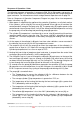
17. Determine the correct amount of water to be added to or closed circuit fluid to be drained from the heat exchanger if the dynamic level is either below the text marking “MINIMUM FLUID LEVEL WITH PUMP OPERATING” or more than 150 mm above this mark. Each 100 mm of fluid level height is equivalent to three (3) litres of closed circuit fluid. 20 mm 40 mm 60 mm • 0.6 litres 1.2 litres 1.8 litres 80 mm 100 mm 120 mm 2.4 litres 3.0 litres 3.6 litres 140 mm 160 mm 180 mm 4.2 litres 4.8 litres 5.
18. Add water to top up the level of the closed circuit fluid in the heat exchanger if required. To add water to the closed circuit fluid: • If not already removed, disconnect the drain line and remove the spring clip from the solar circuit relief valve at the top of the solar storage tank and remove the valve (refer to step 6). Warning: The solar circuit may be under pressure. Take care when removing the solar circuit relief valve, as a sudden discharge of pressurised hot vapour may be experienced.
Pressure Testing the Solar Circuit 21. Close the heat exchanger drain valve. 22. Refit the solar circuit relief valve, orientating the valve outlet to the rear of the solar storage tank. Secure with the spring clip. Reconnect the drain pipe to the valve. 23. Switch on the electrical supply at the isolating switch to the solar storage tank. Warning: Take care not to enter the area inside the solar storage tank behind the access covers whilst the power is on as the electrical circuit will be live.
Remove Closed Circuit Fluid Level Hose 29. Remove the clear hose from the solar storage tank when satisfied the commissioning procedure is complete. To remove the hose: • Ensure the heat exchanger drain valve is closed. • Remove the hose from the side of the storage tank and place the end into a container to collect the closed circuit fluid remaining in the hose. • Replace the plug into the free end of the hose and lay the hose flat on the ground.
Warranty Rheem Solar Water Heater Warranty (Australia only) Warranty conditions 1. This warranty is applicable only to water heaters Service Agent’s premises and the installed site shall be the manufactured from 1st September 2006. owner’s responsibility. 2. The water heater must be installed in accordance with the 5.
Document Revision History Title: Premier Loline Service Instructions Revision A Details of change Service Manual Issued for Premier Loline TM024 Premier Loline Solar Drain back Service Instructions REV: A D.O.I: 12/12/2007 This document is stored and maintained electronically by Document Number: TM024 D.O.I. 12/07 68 Service.