Rheem Australia Pty Ltd ABN 21 098 823 511 SERVICE INSTRUCTIONS Rheem Water Star TM039 Revision: A Published: January 09 W8100401 This document is stored and maintained electronically by Service.
Contents Introduction .......................................................................................................................... 3 Safety Warning .................................................................................................................... 3 Heater Model Identification Number .................................................................................... 3 Specifications...............................................................................................
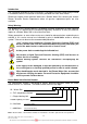
Introduction The information provided in these instructions is based on the water heater being installed in accordance with the Installation Instructions provided with each water heater Should you require further technical advice on a Rheem Water Star, contact your nearest Rheem Australia Service Department where all genuine replacement parts are also available.
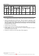
Specifications 800 70 Inlet Outlet T&PR RP¾/20 RP½/15 Element Rating (w) 680 Water Connections T/stat Type T & PR Valve Rating (kPa) 1000 T/stat setting (ºC) Rated Capacity (Litres) 4 Without ECV Capacity 004 Maximum Inlet Pressure (kPa) With ECV Series W81 Model Fixed 800 Preventative Maintenance It is suggested for peak performance that the water heater be serviced annually. 1. Check for discharge from the T&PR valve.
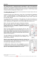
Operation The Rheem Water Star is designed to work in conjunction (in series) with a continuous flow gas water heater, e.g. Rheem Continuous Flow models. It works as a booster water heater to ensure immediate availability of hot water. As such the inlet pipe to the Rheem Water Star is referred to as an inlet pipe, NOT a cold water pipe, as water flowing through this pipe could have a temperature as high as 60ºC.
Components and their Function Temperature and Pressure Relief Valve: A T&PR valve is designed to provide automatic relief to the water heater by discharging water in case of excessive temperature, pressure or both. Never fit a T&PR Valve with a pressure rating greater than that indicated on the product-rating label. Over Temperature Energy Cut Out (E.C.O.
Common Faults When a complaint is lodged about the performance of a hot water system there are a number of causes that should be checked and eliminated. In an attempt to pinpoint the most likely cause it is important to discuss with the customer their reasons for the complaint, the duration of the problem, any change in circumstances or usage and recent weather conditions. This information in conjunction with the following listed common complaints will assist you in locating the most likely cause.
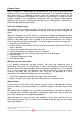
Hot water plumbing leaks If hot water has not been used for a period of time, feeling the temperature of the hot water line may give an indication of water flow if the pipe is warm. The method of checking for plumbing leaks is: 1. Turn off the stopcock on the cold water supply to the water heater. 2. Open a hot tap to ensure the flow of water stops. This will confirm the stopcock is operating correctly. 3. Turn off the hot tap. 4.
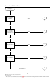
General Fault Finding Chart Fault Diagnosis Is the complaint for no hot water ? YES 1. NO Is the complaint for a high energy bill or insufficient hot water? YES 2. NO Is the complaint for a leaking water heater? YES 3. NO Is the complaint for water too hot? YES 5. Noisy Water Heater TM039 Rheem Water Star Service Instructions REV: A Date of Issue: 02/09 This document is stored and maintained electronically by 4. 9 Service.
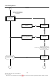
Fault Finding Chart 1 No hot water 1. Warning: Terminals may be live. Personal Protective Equipment must be worn. Test 1 Is 240 volts present at the terminal block? NO Restore power and advise customer YES Is the isolating switch turned off? NO YES Possible fault in household electrical wiring. Continue with diagnosis to confirm water heater is operational.
Fault Finding Chart 1.1 No hot water 1.1 Test 5 Are the thermostat ECO contacts closed? NO Replace thermostat YES Test 6 Are the thermostat contacts closed? NO Is the water in the tank at least 6 degrees lower than the thermostat setting? YES Replace thermostat NO Replace thermostat NO Slide the thermostat out from under the retaining clamp and allow base to cool.
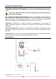
Component Tests 1, 5, & 6 Test 1 With the water heater plugged in and switched on, use a multimeter on the AC volts scale and measure between active and neutral on the terminal block. Normal voltage is 240 volts Test 5 Using a multimeter on the x1 resistance scale, measure between terminals 3 and 4 on the thermostat. The reading should be less than 1Ω. Test 6 Using a multimeter on the x1 resistance scale, measure between terminals 1 and 2 on the thermostat. The reading should be less than 1Ω.
Component Tests 7 & 8 Test 7 Using a multimeter on the x1 resistance scale, measure the resistance of the element across the wires that connect to terminals 2 and 4 of the thermostat. Normal resistance for the element is 6879 ohms. Test 8 Using a multimeter on the x1 resistance scale, measure between active and neutral on the terminal block.
Fault Finding Chart 2 High energy bill/ Insufficient hot water 2 Refer to Rheem sizing guide Has the usage pattern changed recently, ie.additional appliances or people using hot water? Is the heater of sufficient size for the customer‟s ongoing needs? YES NO Recommend a hot water usage pattern that will suit the water heater and the customer‟s needs.
2 Zone Plumbing Option Fault Finding Chart 3 Leaking Water Heater 3.
Fault Finding Chart 4 Water too hot 4 Is the outlet water temperature approx.
Fault Finding Chart 5 Noisy Water Heater 5. Is the noise only evident during the heating cycle? YES Check for: (A) Mineral build-up on the element. (B) Mineral or sludge build-up inm the cylinder (C) Normal noises associated with heating water. YES Refer to water hammer causes, under Common Faults NO Check all other appliances that can generate noise, eg. washing machine, dishwasher, etc. YES Cylinder contracting due to pressure release when hot tap is opened.
Fault Finding Chart 6 6 Electrical Insulation Test Disconnect the wires to the element from the thermostat and megger between each element wire and earth. Is the reading below 1 Megaohm? YES Rewire fuse or reset circuit breaker, if necessary NO Disconnect the remaining wires from the thermostat and megger between each thermostat terminal and earth.
Component Replacement Procedures Draining the Water Heater (Procedure 1) 1. Switch off power at GPO, unplug power cord from GPO and isolate the water supply to the water heater 2. Relieve pressure from the water heater by easing the T&PR valve or through a hot tap. 3. Disconnect the inlet water supply pipe 4. Fit a drain hose to the inlet water connection and run the other end to a drain or safe location. 5. Open the temperature and pressure relief valve to allow air into the system.
12. Purge air from the system through hot taps. 13. Refit the front polystyrene insulation and outer jacket. 14. Restore the power supply to the water heater. Thermostat (Procedure 4) 1. 2. 3. 4. 5. 6. 7. Switch off power at GPO and unplug power cord from GPO. Remove the outer jacket screws. Remove the outer jacket and front polystyrene insulation to expose the water heater. Confirm the wiring is as per the wiring diagram on page 6. Disconnect the wiring to the thermostat.
Outlet Water Connector (Procedure 6) 1. 2. 3. 4. Drain the water heater (refer to procedure 1 on page 19). Remove the outer jacket screws. Remove the outer jacket and front polystyrene insulation to expose the water heater. Disconnect the outlet water pipe from the T&PR valve, transfer valve and outlet water connector by undoing the ¾” brass nuts. 5. Remove the outlet pipe. 6. Remove the two (2) screws retaining the outlet water connector fitting to the bottom chassis. 7.
Element (Procedure 9) 1. 2. 3. 4. 5. 6. 7. 8. 9. Drain the water heater (refer to procedure 1 on page 19). Remove the outer jacket screws. Remove the outer jacket and front polystyrene insulation to expose the water heater. Slide the thermostat out of the retaining clamp Disconnect the T&PR valve drain line and outlet water pipe from the T&PR valve. Disconnect the transfer valve from the cylinder by undoing the ¾” brass nut. Remove the cylinder from the water heater and invert it.
3 Pin Outlet Socket 1. Switch off power at GPO and unplug power cord from GPO. 2. Unplug the continuous flow water heater 3 pin plug from the socket. 3. Remove the outer jacket screws. 4. Remove the outer jacket and front polystyrene insulation to expose the water heater. 5. Confirm the wiring is as per the wiring diagram on page 6. 6. Disconnect the wiring from the active, neutral and earth connectors. 7.
Exploded View Replacement Parts List Item 1 2 3 4 5 6 7 8 9 10 11 12 13 14 15 Description Base – cabinet Insulation - rear T&PR valve Valve connection kit T&PR valve drain pipe ½” Nut – M4 Wiring ass earth (GPO socket) Wiring loom & cord set Wiring loom – thermostat Washer – flat Nut – ½” contite Washer – tooth lock Cone fitting ½” T&PR valve drain fitting Inlet/Outlet fitting TM039 Rheem Water Star Service Instructions REV: A Date of Issue: 02/09 This document is stored and maintained electronically by
Rheem Electric Water Heater Warranty - (Australia Only) WARRANTY CONDITIONS 1. 2. 3. 4. This warranty is applicable only to water heaters st manufactured from 1 June 2008. The water heater must be installed in accordance with 5. the Rheem water heater installation instructions, supplied with the water heater, and in accordance with all relevant statutory and local requirements of the State in which the water heater is to be installed. Where a failed component or water heater is replaced 6.
Document Revision History Title: Service Instructions - Rheem Water Star Revision A Details of change Service Instructions issued for Rheem Water Star TM039 Rheem Water Star Service Instructions REV: A Date of Issue: 02/09 This document is stored and maintained electronically by Document Nº: TM039 D.O.I. 2/09 26 Service.