Use & Care Manual With Installation Instructions for the Installer Electric Hybrid Water Heater The purpose of this manual is twofold: one, to provide the installer with the basic directions and recommendations for the proper installation and adjustment of the water heater; and two, for the owner– operator, to explain the features, operation, safety precautions, maintenance and troubleshooting of the water heater. This manual also includes a parts list.
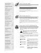
Safety Information Safety Precautions. . . . . . . . 3-4 FOR YOUR RECORDS Write the model and serial numbers here: Installation Instructions # Location. . . . . . . . . . . . . . . . . . 5 # Installing the Water Heater. . . 6 You can find them on a label on the appliance. Water Connections . . . . . . . . . 7 Staple sales slip or cancelled check here. Condensate Drain . . . . . . . . . . 7 Proof of the original purchase date is needed to obtain service under the warranty. Relief Valve. . . . . .
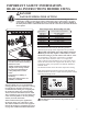
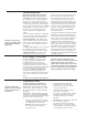
IMPORTANT SAFETY INFORMATION. READ ALL INSTRUCTIONS BEFORE USING. DANGER! WATER TEMPERATURE SETTING Safety and energy conservation are factors to be considered when selecting the water temperature setting of water heater. Water temperatures above 125°F (52°C) can cause severe burns or death from scalding. Be sure to read and follow the warnings outlined on the label pictured below. This label is also located on the water heater near the thermistor access panel.
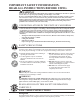
IMPORTANT SAFETY INFORMATION. READ ALL INSTRUCTIONS BEFORE USING. WARNING! For your safety, the information in this manual must be followed to minimize the risk of fire or explosion, electric shock, or to prevent property damage, personal injury, or loss of life. Be sure to read and understand the entire Use and Care Manual before attempting to install or operate this water heater. It may save you time and cost. Pay particular attention to the Safety Instructions.
Installing the water heater The location chosen for the water heater must take into consideration the following: Local Installation Regulations This water heater must be installed in accordance with these instructions, local codes, utility codes, utility company requirements or, in the absence of local codes, the latest edition of the National Electrical Code.
Installing the the water water heater heater Installing Locations that that provide provide optimal optimal efficiency efficiency Locations Heater: Not Ducted Heater: Not Ducted Room size: Larger than 700 ft3 (e.g. 7' x 10' x 10'). 3 Room size: Larger than 700 ftventilation (e.g. 7' x needed. 10' x 10'). Requirements: No additional Requirements: No additional ventilation needed. Heater: Not Ducted Heater: Not Ducted Room size: Smaller than 700 ft3 (e.g. 7' x 10' x 10').
Thermal Expansion NOTICE: The inlet and outlet water nipple remain with the black markings pointed up. Determine if a check valve exists in the inlet water line. Check with your local water utility. It may have been installed in the cold water line as a separate back flow preventer, or it may be part of a pressure reducing valve, water meter or water softener. A check valve located in the cold water inlet line can cause what is referred to as a “closed water system”.
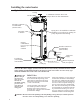
Installing the water heater Typical Installation Ceiling 6" Minimum clearance above heat pump to allow for filter maintenance Air filter Flexible Connection recommended (Such as PEX) Piping Tee to be installed in condensate plumbing to provide access opening for yearly inspection and cleaning.
To Fill the Water Heater ! WARNING: DO NOT turn on the electrical supply or operate this water heater unless it is completely full of water. The tank must be full of water before water heater is turned on. The water heater warranty does not cover damage or failure resulting from operation with an empty or partially empty tank. Make certain the drain valve on the water heater is completely closed. allow the air to vent from the water heater and piping.
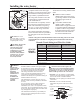
Installing the water heater Electrical Connections continued... CTA Adaptor (Not applicable for all models Conduit connector Ground Screw Junction Box Cover Wire Connections Water heater junction box. ! DO NOT turn on the electrical supply or operate this water heater unless it is completely full of water. A separate branch circuit with copper conductors, overcurrent protective device and suitable disconnecting means must be provided by a qualified electrician.
Hot and Cold Pipe Insulation Installation Install the insulation on the cold water supply inlet and the hot water outlet as shown in the illustration.
Installing the water heater Ducting Requirements Always check with local building and HVAC codes before designing the duct system The water heater may be ducted to the outdoors or another space as described in these instructions. Ducting configurations that does not comply with these guidelines are not supported. DO NOT connect this water heater to existing duct work; it must be ducted separately from other appliances. Ducting approved for HVAC applications is required.
Equivalent feet for Duct Accessories Elbows/Bends Rigid duct elbows and flex bends greater than 45° is considered an elbow. Flexible ducting bends’ inner radius cannot be less than its diameter. If bends with tighter radiuses are needed, a rigid elbow must be used. Maximum number of elbows/bends allowed are shown in [brackets] in Table 2. Terminations/Registers Table 2 equivalent feet for terminations includes the rodent screen.
Installing the water heater Ducting Example: Exhaust/Inlet or both? Both, Inlet and Outlet Ducting to outside of building or another room? Outside building. NOTICE: These seven questions should be answered to ensure correct duct configuration. See Ducting Example. Length of duct from water heater to termination? 20 ft. Flexible or Rigid ducting? Flexible. Diameter of ducting used? 8 in. Diameter Diameter of wall penetrations? 5 in.
Installation Checklist A. Water Heater Location ❑ Close to area of heated water demand. ❑ Indoors and protected from moisture, wet conditions, freezing temperatures (below 32°F (0°C)) and High temperatures (above 140°F (60°C)). ❑ Area free of flammable vapors. ❑ Provisions for Air Circulation (Louvered doors on ducting). ❑ Provisions made to protect area from water damage. ❑ Sufficient room to service heater.
Operating the water heater CAUTION: Hydrogen gas can be produced in a hot water system served by this water heater that has not been used for a long period of time (generally two weeks or more). HYDROGEN GAS IS EXTREMELY FLAMMABLE!! To dissipate such gas and to reduce risk of injury, it is recommended that the hot water faucet be opened for several minutes at the kitchen sink before using any electrical appliance connected to the hot water system.
Local Startup User Interface Current Set Point Current Mode Scald Warning Fault Indicator Mode Toggle Temp & Value Adjustment Next Screen / Option Current Alarm & History Text Display Scroll Available Enable/Disable Clear Alarm ICONS show the current state of the entire system. Enter / Select WiFi Setup & Indicator 1. Current Mode - Illuminated when the system is working on the corresponding mode. 2. Wi-Fi Indicator - Illuminated when the display detects valid connection to a Wi-Fi network.
Local Startup Enabling / Disabling Unit 1) Press the "ON/OFF" button to turn on / enable unit. *Unit will be disabled upon initial startup. 2) Press the "ON/OFF" button to turn off/disable the unit. Adjusting Temperature *Scald warning will automatically appear at 120°F and higher. *Scald warning will automatically appear at 120°F and higher. 1) Press the "UP" button to increase temperature. 2) Press the "DOWN" button to decrease temperature.
Change Mode of Operation Modes of Operation • Energy Saver (Default Mode) • High Demand • Heat Pump • Electric • Vacation Press the "MODE" button to select operating mode. The Energy Saver, default mode is recommended for normal operation, providing maximum savings and fast recovery. Heat pump operation in this mode provides primary heating, with one heating element engaging only if required by demand. Recovery and energy savings vary with the different operating modes.
Local Startup WiFi Setup 1. Press, hold for 5 seconds and release the WiFi button. 2. WiFi LED will start to blink when it is ready to start WiFi setup. 3. WiFi signal will start to broadcast for 30 minutes and user can use EcoNet Application to setup WiFi. 4. If setup is not completed in the next 30 minutes, WiFi will stop broadcasting. User should perform these steps again to re-start WiFi setup. 5. Once correctly connected, LED will turn solid blue.
EcoNet App EcoNet App 2.0 Instructions Download EcoNet app and create profile 1 Open and log into your EcoNet app and select the “Add Product” option on the main equipment screen. 2 Add a location by either selecting “Use my current location” or entering your zip code, then hit “Next”. 3 Place your Water Heater in WiFi setup and click the “Continue” button. 4 Select your WiFi module’s mac address from the network list.
EcoNet App 5 7 22 Return to the app, where you should see the following screen. Click “Available Networks”. The app should proceed to provision your WiFi module using a secure connection. You should see message shown in the image on the left. 6 8 Select your router and enter your password. Click “Connect”. Once connected, product home screen will be displayed.
Care and cleaning of the water heater Draining the Water Heater CAUTION: Shut off power to the water heater before draining water. DANGER: Before manually operating the relief valve, make certain no one will be exposed to the hot water released by the valve. The water drained from the tank may be hot enough to present a scald hazard and should be directed to a suitable drain to prevent injury or damage. In order to drain the water heater, turn off the cold water supply.
Care and cleaning of the water heater Vacation and Extended Shut-Down NOTICE: Refer to the Hydrogen Gas Caution in the Operating Instructions. If the water heater is to remain idle for an extended period of time, the power and water to the appliance should be turned off to conserve energy and prevent a build-up of dangerous hydrogen gas. After a long shut-down period, the water heater’s operation and controls should be checked by qualified service personnel.
Before You Call For Service… Troubleshooting Tips Save time and money! Review the chart on this page first and you may not need to call for service. Problem Possible Causes Rumbling noise Water conditions in your ● Allow a few quarts of water to run from drain valve home caused a build up of to remove sediment settlings. scale or mineral deposits in the water heater.
Troubleshooting Alarm Codes Troubleshooting Tips Save time and money! Review the charts on this section first and you may not need to call for service. The water heater will make an audible beep for notification of Alarms and ! icon. The following steps should be used in determining the Alarm code: 1) Press "Next" button until "Current Alarm" is visible. 2) Press "Down" arrow button to scroll through the active alarms.
Code Troubleshooting Guide Possible Causes A004 Comp.
Troubleshooting Alarm Codes Code Troubleshooting Guide Possible Causes What to Do Heating element or control board failure. Heater disabled. Disconnect power to unit 2. Check resistance on element per included Ohm Reading Chart 3. If acceptable ohm reading is present, replace board 4. If ohm reading is not as it should be per included chart, replace Elements mis-wired or control board failure. Heater disabled. 1. Disconnect power to unit. 2. Check wiring connection to heating element. 3.
Code Troubleshooting Guide Possible Causes What to Do A502 Time Clock needs to be programmed A503 Time Clock not advancing time properly T504 WiFi Chip Communication Error A900 Controller Fault: Call Tech Service T901 Controller Fault: Call Tech Service Controller malfunction. Heater disabled. Replace Control Board A902 Controller Fault: Call Tech Service A903 Controller Fault: Call Tech Service A904 Controller Fault: Call Tech Service A905 Controller Fault: Call Tech Service A906 Power Board Temp.
CTA Module Wiring Water Heater Junction Box Conduit connector CTA Adaptor (Not applicable for all models Junction Box Cover Ground Screw Wire Connections A separate branch circuit with copper conductors, overcurrent protective device and suitable disconnecting means must be provided by a qualified electrician. All wiring must conform to local codes or latest edition of National Electrical Code ANSI/NFPA 70. 1.
JA13 Offline Schedule Setting & Battery Replacement Front Cover BR2032 Battery Control Board Assembly Before uploading and enabling JA13 offline schedule (Utility Contractor Only): 1. Power ON Water Heater. 2. Press, hold for 5 seconds and release the WiFi button. 3. WiFi LED will start to blink when it is ready to start WiFi setup. 4. WiFi signal will start to broadcast for 30 minutes and user can use the EcoNet Contractor Portal and Contractor Application to setup JA13 Offline Schedule. 5.
Demand Response (CTA-2045/JA13) Installations A thermostatic mixing valve conforming to ASSE 1017 shall be installed on the hot water supply line following all manufacturer installation instructions (mixing valve is not included with the unit). Nominal 3/4" size mixing or tempering valve (refer to warning above). Follow mixing or tempering valve manufacturer's instructions for installation of the valve.
Replacement Parts. Instructions For Placing a Parts Order Address parts orders to the distributor or store where the heater was purchased. * NOTICE: Check the water heater's rating label on the front of the unit for the acceptable element wattage. All parts orders should include: ! CAUTION: For your safety DO NOT attempt repair of electrical wiring, heating elements, heat pump or electronic controls. Refer repairs to qualified service personnel.
Replacement Parts. Part Number Description Part Number Description AP20142 Air Filter AP10869ML-7 Element 4.
Cavity Insert Instructions The following instructions are intended for qualified service personnel ONLY, and should only be done when necessary. In order to replace the ECO,thermistor or heating element, remove the cavity insert crossbar by following the instructions below: ECO Reset Button Disconnect all power to unit before to starting maintenance. Remove the jacket access panel(s) and insulation. Rotate the crossbar up and down until it breaks away from the remainder of the cavity insert.
Wiring Diagram OVERLAY LEAK SENSOR LEAK DETECT SOV OPEN SOV CLOSED MOTOR A MOTOR B SOV DETECT MODEL ID CTA-2045 208-240V, 1 PH.
Notes 37
Notes 38
Notes 39
IF YOU NEED SERVICE 1. Should you have any questions about your new water heater, or if it requires adjustment, repair, or routine maintenance, it is suggested that you first contact your installer, plumbing contractor or previously agreed upon service agency. In the event the firm has moved, or is unavailable, refer to the telephone directory, commercial listings or local utility for qualified service assistance. 2.