
Use and Care Manual

12
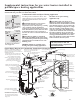
The water heater must be installed with the factory supplied draft hood in place.
Venting
This water heater is a Category I -Natural
Draft appliance. Vent connectors must be
attached to the draft hood outlet to connect
the water heater to the gas vent or chimney.
The vent connectors must be the same size
(diameter) as the draft hood or larger, never
smaller.
For proper venting in certain installations a
larger vent connector size may be needed.
Consult the Vent Tables in Appendix G of
the latest version of the National Fuel Gas
Code (ANSI standard Z223.1 or NFPA 54).
Multi-story and common venting is
permitted. Consult the latest version
of the National Fuel Gas Code (ANSI
standard Z223.1 or NFPA 54).
Horizontal vent connectors must be pitched
upward to the chimney at least 1/4 in. per
foot of length. Single wall vent connectors
must be at least 6 in. from adjacent
unprotected combustible surface. Vent joints
must be securely fastened by sheet metal
screws or other approved method.
Test for spillage at the draft hood relief
opening after 5 minutes of main burner
operation. Use a flame of a match or
candle or smoke. The flame or smoke
should be pulled into the draft hood’s relief
opening(s).
DANGER: Failure to install
the draft hood and properly
vent the water heater to the
outdoors as outlined in the
Venting section of this manual
will result in unsafe operation
of the water heater causing
bodily injury, explosion, fire or
death. To avoid the risk of fire,
explosion, or asphyxiation from
carbon monoxide, NEVER
operate the water heater unless
it is properly vented and has
adequate air supply for proper
operation as outlined in the
Venting section of this manual.
Insulation Blankets
Insulation blankets, available to the
general public, for external use on gas
water heaters are not necessary. The
purpose of an insulation blanket is to
reduce the standby heat loss encountered
with storage tank heaters. This water
heater meets or exceeds the National
Appliance Energy Conservation Act
standards with respect to insulation and
standby loss requirements making an
insulation blanket unnecessary.
The manufacturer’s warranty does not
cover any damage or defect caused
by installation, attachment or use of
any type of energy saving or other
unapproved devices (other than those
authorized by the manufacturer) into,
onto or in conjunction with the water
heater. The use of unauthorized energy
saving devices may shorten the life of the
water heater and may endanger life and
property.
The manufacturer disclaims any
responsibility for such loss or injury
resulting from the use of such
unauthorized devices.
CAUTION: If local codes require
the application of an external
insulation blanket to this water heater,
pay careful attention to the following
so as not to restrict the proper function
and operation of the water heater:
● DO NOT cover the operating or
warning labels attached to the water
heater or attempt to relocate them on
the exterior of insulation blanket.
DO NOT apply insulation to the top
of the water heater. This will interfere
with the safe operation of the draft
hood.
DO NOT cover the burner access door,
jacket door, gas control (thermostat)/
gas valve or pressure and temperature
relief valve.
DO NOT apply insulation to the
bottom of the water heater or the
area where the combustion air inlet
openings are located. This area must
be unobstructed so as not to restrict
combustion air flow to the burner.
Inspect the insulation blanket
frequently making certain it has not
sagged and is restricting the air flow
to the combustion air inlet openings
(perforation holes) located around the
lower perimeter of the water heater
jacket. This could result in an unsafe
operating condition.
WARNING: If local codes
require external application of
insulation blanket kits the
manufacturer’s instructions
included with the kit must be
carefully followed.
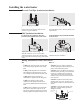
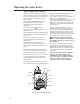
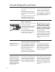
Heat Traps
For increased energy efficiency, some
water heaters have been supplied with
factory installed 3/4 in. NPT heat traps
in the hot outlet line and cold water inlet
line.
These heat traps may require a minimum
of one (1) 90° 3/4 in. NPT elbow and
may require an additional 90° 3/4
in. NPT elbow or a 3/4 in. coupling,
depending on your installation needs. See
Illustration of nipples and heat traps on
page 23.
Installing the water heater