GK6072 60" & 72" Rear Discharge Finishing Mowers Published 08/01 P/N 00767471C OPERATOR'S MANUAL This Operator's Manual is an integral part of the safe operation of this machine and must be maintained with the unit at all times. READ, UNDERSTAND, and FOLLOW the Safety and Operation Instructions contained in this manual before operating the equipment. RHINO® 1020 S. Sangamon Ave. Gibson City, IL 60936 800-446-5158 Email: parts@servis-rhino.com © 2004 Alamo Group Inc. $0.
TO THE OWNER/OPERATOR/DEALER All implements with moving parts are potentially hazardous. There is no substitute for a cautious, safe-minded operator who recognizes the potential hazards and follows reasonable safety practices. The manufacturer has designed this implement to be used with all its safety equipment properly attached to minimize the chance of accidents. BEFORE YOU START!! Read the safety messages on the implement and shown in your manual.
BE SAFE! BE ALERT! BE ALIVE! BE TRAINED before operating the Mower! Safety Training Makes the Difference In order to reduce accidents and enhance the safe operation of mowers, Alamo Group Ag Division, in cooperation with other industry manufacturers has developed the AEM/FEMA Industrial and Agricultural Mower Safety Practices video and guide book. The video will familiarize and instruct mower-tractor operators in safe practices when using industrial and agricultural mowing equipment.
Alamo Group Ag.
TABLE OF CONTENTS SAFETY SECTION ......................................................................................................................................... 1-1 Safety Information .......................................................................................................................................... 1-2 Decal Location ..............................................................................................................................................
SAFETY SECTION Safety Section 1-1
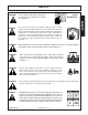
SAFETY SAFETY A safe and careful operator is the best operator. Safety is of primary importance to the manufacturer and should be to the owner/operator. Most accidents can be avoided by being aware of your equipment, your surroundings, and observing certain precautions. The first section of this manual includes a list of Safety Messages that, if followed, will help protect the operator and bystanders from injury or death.
SAFETY PELIGRO! Si no lee Ingles, pida ayuda a alguien que si lo lea para que le traduzca las medidas de seguridad. (SG-3) DANGER! Never operate the Tractor or Implement until you have read and completely understand this Manual, the Tractor Operator’s Manual, and each of the Safety Messages found in the Manual or on the Tractor and Implement. Learn how to stop the tractor engine suddenly in an emergency.
SAFETY DANGER! Never allow children or other persons to ride on the Tractor or Implement. Falling off can result in serious injury or death. SAFETY (SG-10) DANGER! Never allow children to operate or ride on the Tractor or Implement. (SGM-11) WARNING! Do not mount the Tractor while the tractor is moving. Mount the Tractor only when the Tractor and all moving parts are completely stopped. (SG-12) DANGER! Start tractor only when properly seated in the Tractor seat.
SAFETY WARNING! Before transporting the Tractor and Implement, determine the safe transport speeds for you and the equipment. Make sure you abide by the following rules: 1. Test the tractor at a slow speed and increase the speed slowly. 2. 3. Apply the Brakes smoothly to determine the stopping characteristics of the Tractor and Implement. As you increase the speed of the Tractor the stopping distance increases. Determine the maximum safe transport speed for you and this Equipment.
SAFETY SAFETY DANGER! DANGER! WARNING! DANGER! KEEP AWAY FROM ROTATING ELEMENTS to prevent entanglement (SG-24) and possible serious injury or death. Never allow children to play on or around Tractor or Implement. Children can slip or fall off the Equipment and be injured or killed. Children can cause the Implement to shift or fall crushing themselves or others. (SG-25) Do not exceed the rated PTO speed for the Implement.
SAFETY DANGER! DANGER! The rotating parts of this machine have been designed and tested for rugged use. However, they could fail upon impact with heavy, solid objects such as steel guard rails and concrete abutments. Such impact could cause the broken objects to be thrown outward at very high velocities. To reduce the possibility of property damage, serious injury, or even death, never allow the cutting blades to contact such obstacles.
SAFETY DANGER! Replace bent or broken blade with new blades. NEVER ATTEMPT TO STRAIGHTEN BLADES SINCE THIS WILL LIKELY CRACK OR OTHERWISE DAMAGE THE BLADE WITH SUBSEQUENT FAILURE AND POSSIBLE SERIOUS INJURY FROM THROWN BLADES. SAFETY (SGM-10) WARNING! Do not mow with two machines in the same area except with Cab tractors with the windows closed. (SGM-11) DANGER! Always disconnect the main PTO Driveline from the Tractor before performing service on the Mower.
SAFETY DANGER! DANGER! All Safety Shields, Guards and Safety devices including (but not limited to) - the Discharge Deflectors, Steel Guards, Gearbox Shields, Belt Shileds, and PTO Shields should be used and maintained in good working condition. All safety devices should be inspected carefully at least daily for missing or broken components. Missing, broken, or worn items must be replaced at once to reduce the possibility of injury or death from thrown objects, entanglement, or blade contact.
SAFETY SAFETY DANGER! Replace bent or broken blade with new blades. NEVER ATTEMPT TO STRAIGHTEN OR WELD ON BLADES SINCE THIS WILL LIKELY CRACK OR OTHERWISE DAMAGE THE BLADE WITH SUBSEQUENT FAILURE AND POSSIBLE SERIOUS INJURY FROM THROWN BLADES.
SAFETY 16 8 6A 14A 5 15 1 16 9 6 14 8A 13 2 3 4 12 13 11 4A 14 7 20 10 21 17 23 22 ITEM PART NO.
SAFETY SAFETY 1 - 00725746 3 - 00755742 4 - 00756004 5 - 00756005 2 - 00749117 - Not Shown (See Inside Front Cover of Manual) 7 - 00758194 6 - 00756494 8 - 00760657 9 - D103 GK6072 08/01 © 2004 Alamo Group Inc.
11 - 00755691 4A - 00775933 12 - 00763977 13 - 99101 14 -00771819 17 - 00776481 8A - 00773723
SAFETY FEDERAL LAWS AND REGULATIONS SAFETY This section is intended to explain in broad terms the concept and effect of federal laws and regulations concerning employer and employee equipment operators. This section is not intended as a legal interpretation of the law and should not be considered as such. Employer-Employee Operator Regulations U.S. Public Law 91-596 (The Williams-Steiger Occupational and Health Act of 1970) OSHA This Act Seeks: “...
INTRODUCTION SECTION Introduction Section 2-1
INTRODUCTION This Rotary Mower is designed with care and built with quality materials by skilled workers. Proper assembly, maintenance, and operating practices, as described in this manual, will help the owner/operator get years of satisfactory service from the machine. INTRODUCTION The purpose of this manual is to familiarize, and instruct. The Assembly Section instructs the owner/operator in the correct assembly of the Mower using standard and optional equipment.
INTRODUCTION INTRODUCTION Your RHINO GK mower is designed for light-duty cutting such as lawn maintenance plus small weed and grass control. With a reasonable amount of preventive maintenance, your Mower will provide years of dependable service. DANGER! NEVER ALLOW CHILDREN TO OPERATE, RIDE ON, OR COME CLOSE TO MOWER OR TRACTOR.
INTRODUCTION ATTENTION OWNER/OPERATOR INTRODUCTION BEFORE OPERATING THIS MACHINE: 1. Carefully read the Operator’s Manual, completely understand the Safety Messages and instructions, and know how to operate correctly both the tractor and Mower. 2. Fill out the Warranty Card in full. Be sure to answer all questions, including the Serial Number of the Mower. Mail within 30 days of delivery date of this implement.
ASSEMBLY SECTION Assembly Section 3-1
ASSEMBLY The GK60 & 72 Mowers will attach to most tractors with Cat. I Three-Point hitch and a 540 RPM PTO. DO NOT EXCEED HORSEPOWER RECOMMENDATIONS. DANGER! Operating with PTO speed over 540 RPM can cause excessive vibration with subsequent machine failure which can cause serious injury or even death. Never exceed 600 RPM. DEALER SET-UP INSTRUCTIONS Assembly of this mower is the reponsibility of the Rhino dealer.
ASSEMBLY A-FRAME ATTACHMENT (cont'd.) Install floating hitch pins to main frame using either the standard or extended hitch postions. Exploded view shows standard position FIGURE 2. To install in extended position move flats (1) forward and place bushings (2) in rear holes and bushing (3) at center hole. FIGURE 3.
OPERATION SECTION Operation Section 4-1
OPERATION The safe operation of this machine is the responsibility of the operator. The operator should be familiar with the cutter and tractor and all safety practices before starting operation. This mower is designed for lawn or grass mowing. It is not designed for rough conditions or heavy weed mowing. It is equipped with suction type blades for best results in lawn mowing. Always operate tractor PTO at 540 rpm.
OPERATION DRIVELINE ATTACHMENT TO TRACTOR 1. Grab and pull collar on end of attaching yoke toward cutter. 2. Slide yoke (with collar depressed) onto PTO shaft. 3. Move yoke back and forth until locking collar clicks forward and locks the yoke in place. WARNING! When attaching PTO yoke to tractor PTO shaft, it is important that spring activated locking collar slides freely and is seated in groove on PTO shaft. WARNING! Be sure PTO shielding and all other shielding is installed and is in good condition.
OPERATION Enter the area to cut with the cutter operating at PTO speed and, if it becomes necessary to temporarily regulate engine speed during operations, increase or decrease the throttle gradually. To transport, disengage the PTO, raise full transport height. CUTTING SPEED Proper ground speed for cutting will depend upon the height, type, and density of material to be cut. Normally, ground speed will range from 1-1/2 to 3 mph.
OPERATION BEFORE OPERATING OR TRANSPORTING THIS MOWER Always display this SMV emblem (FIGURE 1) on the rear of the tractor transporting this mower where it is clearly visible to oncoming traffic. Prominent display of this symbol will help the operator avoid accidents which could cause injury or possibly death. FIGURE 1 DRIVELINE LENGTH CHECK PROCEDURE A loose shaft could slip off and result in personal injury or dfamage to cutter.
OPERATION DRIVELINE LENGTH Raise mower to full transport or until driveline just hits deck at front. If distance between colored tape and outer shield tube is 1-9/16 or less, drive tubes should be shortened per Figure 4. Always maintain 1-9/16 clearance when operated in shortest working position. shorten inner and outer guard tubes equally. Shorten inner and outer sliding profiles by the same amount that the shield tubes were shortened. Round off all sharp edges and remove burrs. Grease sliding profiles.
OPERATION TROUBLESHOOTING PROBLEM POSSIBLE CAUSE REMEDY STREAKING Slow Blade Speed Worn Blade Tips Operate PTO at 540 RPM. Replace with Genuine RHINO Blades. See your Rhino dealer. Sharpen blades uniformly. Slow ground speed of tractor but keep engine running at full PTO rpm. Cutting lower will help. Slow down until cured. Tighten per instructions. Apply belt dressing or replace with special RHINO belt. Tighten blade bolt securely. (Note: Left Hand threads Torque to 85 ft. lbs.
OPERATION TROUBLESHOOTING PROBLEM POSSIBLE CAUSE BELT SLIPPAGE Mower overloading, material too Reduce tractor ground speed but tall or heavy maintain full PTO rpm. Cut material twice, one high pass and then mow at desired height. Cut a partial swath. Oil on belt from over lubrication Be careful not to over lubricate. Clean lubricant from belt and pulleys with clean rag. Replace oil soaked belt. Belt hung up or rubbing Check belt for free travel in pulleys and belt guides.
MAINTENANCE SECTION Maintenance Section 5-1
MAINTENANCE Before operating your Finishing Mower, make sure it is properly lubricated and thoroughy inspected. Only a minimum of time and effort is required to regularly lubricate and maintain this machine to provide long life and trouble free operation. WARNING! Always disengage the PTO before raising the Rotary Cutter for transporting or making adjustments. LUBRICATION INFORMATION Do not let excess grease collect on or around parts, particulary when operating in sandy areas.
MAINTENANCE GEARBOX The Gearbox has been filled with lubricant to the Test Plug Level prior to shipment. However, you should check the oil level at Test Plug before operating, and frequently thereafter. The gearbox should not require additional lubricant unless the box is cracked or a seal is leaking. It is recommended that the oil level plug be removed after every 8 to 10 hours of operation and oil added until it runs out Test Plug hole. The Test Plug is located on the side of the Gearbox.
MAINTENANCE DRIVELINE LUBRICATION Grease Fittings are located on the Cross Assembly of each U-Joint and on the telescoping tubes. Grease the U-Joint after each 8 hours of use. Figure 5. Do not force grease through the Needle Cup Assemblies. FIGURE 5 The telescoping PTO shaft inside the shielding must be lubricated daily. Figure 6. Disconnect driveline from tractor and pull halves apart. Insert grease into outer profile cavity on half attached to gearbox and spread evenly. Install driveline halves together.
MAINTENANCE BLADE SERVICING Inspect blades before each use to determine that they are properly installed and in good condition. Replace any blade that is bent, excessively nicked, worn, or has any other damage. Small nicks can be ground out when sharpening. Use only original equipment blades on this cutter. They are made of special heat-treated alloy steel. Substitute blades may not meet specification and may fail in a hazardous manner that could cause injury.
MAINTENANCE 4 2 3 1 5 3/4" FIGURE 8 10 LBS. Locknut MAINTENANCE Flatwasher Spacer Flatwasher Bolt BELT ADJUSTMENT PROCEDURE (All Models except 11') Adjust the tension in the drive belts, item1, properly so that they deflect 3/4" when a force of approximately 10 lb. is applied as indicated. Tighten drive belts by loosening nut, items 2 & 5, and turn nut, item 3 against the anchor plate until proper tension is reached. DO NOT OVERTIGHTEN. Tighten jam nut, item 4., and nut item 2.
MAINTENANCE STORAGE Your rotary mower represents an investment from which you should get the greatest possible benefit. Therefore, when the season is over, the cutter should be thoroughly checked and prepared for storage so that a minimum amount of work will be required to put it back into operation for the next season. The following are suggested storage procedures: 1. 2. 3. 4. 5. 6. Thoroughly clean the cutter. Lubricate the cutter as covered in Maintenance Section.
MAINTENANCE BLADE SPINDLE SERVICE INSTRUCTIONS (FIGURE 10) DISASSEMBLY 1. Remove adjusting nut #3. 2. Support spindle housing #2 under flange and drive out shaft assembly #1. CAUTION ! Use tube on top end of shaft to protect grease fitting. 3. Remove bearing cups from housing. Remove lower bearing from shaft assembly by inserting punch through hole in shaft hub and drive bearing off shaft. Once bearing has been moved 3/8" - 1/2" up shaft, lay flatbars on either side of the shaft and support across vice..
MAINTENANCE SERVICING DRIVELINE SHIELDS (Figure 11) 1. Remove locking screw #1. 2. Twist shield tube in relation to cone to align white tab with slot in cone. 3. Pull on shield tube to remove complete shield from assembly. 4. Shield Bearing is split and can be removed by pulling ends apart. Note positioning of bearing before removing. 5. To replace flex cone on shield tube, cut old cone off with knife. Remove chain assembly. Heat collar of the new one in a water bath (approx 80 deg. C or 176 deg.
SERVIS-RHINO LIMITED WARRANTY 1. LIMITED WARRANTIES 1.01.Servis-Rhino warrants for one year from the purchase date to the original non-commercial, governmental, or municipal purchaser (“Purchaser”) and warrants for six months to the original commercial or industrial purchaser (“Purchaser”) that the goods purchased are free from defects in material or workmanship. 1.02.
TO THE OWNER/OPERATOR/DEALER To keep your implement running efficiently and safely, read your manual thoroughly and follow these directions and the Safety Messages in this Manual. The Table of Contents clearly identifies each section where you can easily find the information you need. The OCCUPATIONAL SAFETY AND HEALTH ACT (1928.51 Subpart C) makes these minimum safety requirements of tractor operators: REQUIRED OF THE OWNER: 1. 2. 3. 4.
GK60/72-OMWPL-08/01 Printed U.S.A.
An Alamo Group Company SERVIS-RHINO® 1020 S. Sangamon Ave. Gibson City, IL 60936-9907 Please fold (do not tear), tape, and drop in any mailbox. PLEASE FILL OUT OWNER WARRANTY REGISTRATION INFORMATION SIGN, AND DROP LAST COPY IN ANY MAILBOX. IMPORTANT! TO PLACE THIS WARRANTY IN EFFECT, THIS WARRANTY REGISTRATION MUST BE FILLED OUT, SIGNED, AND MAILED WITHIN 30 DAYS OF DELIVERY DATE OF THIS MACHINE. DEALER AND PURCHASER MUST SIGN.
SERVIS-RHINO WARRANTY REGISTRATION INFORMATION MONTH Servis-Rhino Model Serial No. DAY YEAR Purchase Date Purchaser Last Name Street & No., RFD, Box, &/or Apt. No. First Name City M.I.
2. REMOVE WHITE COPY FOR CUSTOMER RECORDS. 3. REMOVE YELLOW COPY FOR DEALERS RECORDS. 4. MAIL LAST CARD POSTAGE FREE. SERVIS-RHINO® WARRANTY REGISTRATION INFORMATION MONTH Servis-Rhino Model Serial No. Purchaser Last Name Street & No., RFD, Box, &/or Apt. No. City DAY YEAR Purchase Date First Name M.I.
2. REMOVE WHITE COPY FOR CUSTOMER RECORDS. 3. REMOVE YELLOW COPY FOR DEALERS RECORDS. 4. MAIL LAST CARD POSTAGE FREE. SERVIS-RHINO® WARRANTY REGISTRATION INFORMATION MONTH Servis-Rhino Model Serial No. Purchaser Last Name Street & No., RFD, Box, &/or Apt. No. City DAY YEAR Purchase Date First Name M.I.