FN10/FN15 NITRO HEAVY-DUTY FLEX-WING ROTARY CUTTER Published 02/10 Part NO. 00779794C OPERATOR’S MANUAL This Operator's Manual is an integral part of the safe operation of this machine and must be maintained with the unit at all times. READ, UNDERSTAND, and FOLLOW the Safety and Operation Instructions contained in this manual before operating the equipment. C01Cover RHINO ® 1020 S. Sangamon Ave. Gibson City, IL 60936 800-446-5158 Email: parts@servis-rhino.com ©2010 Alamo Group Inc. $0.
To the Owner/Operator/Dealer All implements with moving parts are potentially hazardous. There is no substitute for a cautious, safe-minded operator who recognizes the potential hazards and follows reasonable safety practices. The manufacturer has designed this implement to be used with all its safety equipment properly attached to minimize the chance of accidents. BEFORE YOU START!! Read the safety messages on the implement and shown in your manual.
In order to reduce accidents and enhance the safe operation of mowers, Alamo Group Ag Division, in cooperation with other industry manufacturers has developed the AEM/FEMA Industrial and Agricultural Mower Safety Practices video and guide book. The video will familiarize and instruct mower-tractor operators in safe practices when using industrial and agricultural mowing equipment.
Alamo Group Ag. Division is willing to provide one (1) AEM Mower Safety Practices Video Please Send Me: VHS Format – AEM/FEMA Mower Operator Safety Video DVD Format – AEM/FEMA Mower Operator Safety Video Mower Operator’s Manual AEM Mower Operator’s Safety Manual Requester Name Phone: Requester Address: City State Zip Code Mower Model: Serial Number: Date Purchased: Dealer Salesperson: Dealership Name: Dealership Location: Mail to: AEM Video Services 1502 E.
TABLE OF CONTENTS SAFETY SECTION .............................................................................................................. 1-1 General Safety Instructions and Practices ......................................................................................................... 1-2 Operator Safety Instructions and Practices ....................................................................................................... 1-3 Equipment Operation Safety Instructions and Practices .......
Starting the Tractor .......................................................................................................................................... 4-29 Brake and Differential Lock Setting .................................................................................................................. 4-29 Operating the Mower Wings ............................................................................................................................ 4-29 Transport Position ................
SAFETY SECTION Safety Section 1-1 © 2010 Alamo Group Inc.
SAFETY General Safety Instructions and Practices SAFETY A careful operator is the best operator. Safety is of primary importance to the manufacturer and should be to the owner/operator. Most accidents can be avoided by being aware of your equipment, your surroundings, and observing certain precautions. The first section of this manual includes a list of Safety Messages that, if followed, will help protect the operator and bystanders from injury or death.
SAFETY Engine Exhaust, some of its constituents, and certain vehicle components contain or emit chemicals known to the state of California to cause cancer and birth defects or other reproductive harm. (SG-30) Battery posts, terminals and related accessories contain lead and lead compounds, chemicals known to the state of California to cause cancer, birth defects or other reproductive harm. (SG-31) The rotating parts of this machine continue to rotate even after the PTO has been turned off.
SAFETY Always read carefully and comply fully with the manufacturer’s instructions when handling oil, solvents, cleansers, and any other chemical agent. (SG-22) SAFETY KEEP AWAY FROM ROTATING ELEMENTS to prevent entanglement and possible serious injury or death. (SG-24) Never allow children to play on or around Tractor or Implement. Children can slip or fall off the Equipment and be injured or killed. Children can cause the Implement to shift or fall crushing themselves or others.
SAFETY Avoid contact with hot surfaces of the engine or muffler. Use gloves and eye protection when servicing hot components. Contact with a hot surface or fluid can cause serious injury from burns or scalding. (SG-38) Do not put hands or feet under mower decks. Blade Contact can result in serious injury or even death. Stay away until all motion has stopped and the decks are securely blocked up. (SGM-09) Do not operate the implement while wearing loose fitting clothing.
SAFETY SAFETY Do not operate Mower if excessive vibration exists. Shut down PTO and the Tractor engine. Inspect the Mower to determine the source of the vibration. If Mower blades are missing or damaged replace them immediately. Do not operate the mower until the blades have been replaced and the Mower operates smoothly. Operating the Mower with excessive vibration can result in component failure and broken objects to be thrown outward at very high velocities.
SAFETY Do not operate this Equipment with hydraulic oil or fuel leaking. Oil and fuel are explosive and their presence could present a hazard. Do not check for leaks with your hand! High-pressure oil streams from breaks in the line could penetrate the skin and cause tissue damage including gangrene. To check for a hose leak, SHUT the unit ENGINE OFF and remove all hydraulic pressure. Wear oil impenetrable gloves, safety glasses and use Cardboard to check for evidence of oil leaks.
SAFETY SAFETY There are obvious and hidden potential hazards in the operation of this Mower. REMEMBER! This machine is often operated in heavy brush and in heavy weeds. The Blades of this Mower can throw objects if shields are not properly installed and maintained. Serious injury or even death may occur unless care is taken to insure the safety of the operator, bystanders, or passersby in the area. Do not operate this machine with anyone in the immediate area.
SAFETY Follow these guidelines to reduce the risk of equipment and grass fires while operating, servicing, and repairing the Mower and Tractor: -Equip the Tractor with a fire extinguisher in an accesible location. -Do Not operate the Mower on a Tractor with an underframe exhaust. -Do Not smoke or have an open flame near the Mower and Tractor. -Do Not drive into burning debris or freshly burnt areas. -Ensure slip clutches are properly adjusted to prevent excessive slippage and plate heating.
SAFETY SAFETY Rotary Mowers are capable under adverse conditions of throwing objects for great distances (300 feet or more) and causing serious injury or death. Follow safety messages carefully.
SAFETY Connecting or Disconnecting Implement Safety Instructions and Practices DO NOT use a PTO adapter to attach a non-matching Implement driveline to a Tractor PTO. Use of an adapter can double the operating speed of the Implement resulting in excessive vibration, thrown objects, and blade and implement failure. Adapter use will also change the working length of the driveline exposing unshielded driveline areas. Serious bodily injury and/or equipment failure can result from using a PTO adapter.
SAFETY Transporting Safety Instructions and Practices Be particularly careful when transporting the Implement with the Tractor. Turn curves or go up hills only at a low speed and using a gradual steering angle. Rear mounted implements move the center of gravity to the rear and remove weight from the front wheels. Make certain, by adding front ballast, that at least 20% of the tractor’s weight is on the front wheels to prevent rearing up, loss of steering control or Tractor tip-over.
SAFETY Transport only at speeds where you can maintain control of the equipment. Serious accidents and injuries can result from operating this equipment at high speeds. Understand the Tractor and Implement and how it handles before transporting on streets and highways. Make sure the Tractor steering and brakes are in good condition and operate properly. Before transporting the Tractor and Implement, determine the proper transport speeds for you and the equipment.
SAFETY Secure the Implement for transport before traveling on public roads. For pull-type Implements, secure the center axle using cylinder stops or transport pin and properly attach a safety chain between the Implement and Tractor. Secure wings in upright position on folding Implements using wing transport locks. (STI-7) SAFETY Always keep a careful lookout and use extreme care when working around overhead obstructions and electrical power lines. The Implement wing can be over 10 feet high.
SAFETY Never work under the Implement, the framework, or any lifted component unless the Implement is securely supported or blocked up to prevent sudden or inadvertent falling which could cause serious injury or even death. (SG-14) Never attempt to lubricate, adjust, or remove material from the Implement while it is in motion or while tractor engine is running. (SG-20) Perform service, repairs and lubrication according to the maintenance section.
SAFETY SAFETY PARTS INFORMATION Rhino mowers use balanced and matched system components for blade carriers, blades, cuttershafts, knives, knife hangers, rollers, drivetrain components, and bearings. These parts are made and tested to Rhino specifications. Non-genuine "will fit" parts do not consistently meet these specifications. The use of “will fit” parts may reduce mower performance, void warranties, and present a safety hazard. Use genuine Rhino mower parts for economy and safety.
SAFETY Decal Location NOTE: Rhino supplies safety decals on this product to promote safe operation. Damage to the decals may occur while in shipping, use, or reconditioning. Rhino cares about the safety of its customers, operators, and bystanders, and will replace the safety decals on this product in the field, free of charge (Some shipping and handling charges may apply). Contact your Rhino dealer to order replacement decals SAFETY FN10/FN15 NITRO 02/10 © 2010 Alamo Group Inc.
SAFETY SAFETY ITEM PART NO. QTY TYPE DESCRIPTION 1. 2. 3. 4. 5. 6. 7. 8. 9. 10. D389 D388 D390 D417 00753840 D401 999403 00760657 00756004 11. 12. 13. 14. 15. 16. 17. 18. 19. 20. 21. 22. 23. 24. 25. 26. 27. 28. 29. 30. 31. 32. 33.
SAFETY Decal Description Multi Hazard Decal Sheet Decal D389 consists of the following multi-hazards. FN10/FN15 NITRO 02/10 © 2010 Alamo Group Inc.
SAFETY Driveline Hazards SAFETY P/N D388 Decal D388 consists of the following multi-hazards. FN10/FN15 NITRO 02/10 © 2010 Alamo Group Inc.
SAFETY Multi Hazard Decal Sheet P/N D390 FN10/FN15 NITRO 02/10 © 2010 Alamo Group Inc. Safety Section 1-21 SAFETY Decal D390 consists of the following multi-hazards.
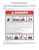
SAFETY SAFETY IMPORTANT! Always replace blades in pairs. P/N D417 DANGER! wings. Stay clear when lowering or raising P/N 00753840 1000 RPM P/N D401 DANGER! Keep everyone clear when lifting, folding, and working under raised components. Block securely before working under mower. Install Weight Box and Weight (Min. of 700lbs) before operating to prevent turning over the center section which can cause SERIOUS BODILY INJURY or DEATH. Without weight, Do not fold wing.
SAFETY For safety and to guarantee optimum product reliability always use genuine RHINO replacement parts. P/N 00760657 P/N 00756004 NAME LOGO - FL10 P/N FL10 NAME LOGO - FL15 P/N FL15 FN10/FN15 NITRO 02/10 © 2010 Alamo Group Inc. Safety Section 1-23 SAFETY DANGER! Guard Missing, Do Not Operate. If you see this decal, Do Not Operate the mower until the shield has been replaced.
SAFETY SAFETY NAME LOGO: NITRO P/N D558 NAME LOGO: NITRO P/N D557 Blade Rotation Counter Clockwise. P/N D137 Blade Rotation Clockwise. P/N D138 FN10/FN15 NITRO 02/10 © 2010 Alamo Group Inc.
SAFETY INFORMATION - 5 Year Gearbox Warranty P/N 00771283 P/N 00771284 Logo Product Name: Rhino P/N 99102 Logo Product Name: Rhino P/N D302 FN10/FN15 NITRO 02/10 © 2010 Alamo Group Inc.
SAFETY SAFETY Logo Product Name: Rhino P/N D303 Slow Moving Vehicle Decal. Keep SMV reflector clean and visible. DO NOT transport or operate without the SMV. P/N 03200347 Red Reflector. Keep reflectors clean and visible. P/N 1458392 Amber Reflector. Keep reflectors clean and visible. P/N 1458393 FN10/FN15 NITRO 02/10 © 2010 Alamo Group Inc.
SAFETY Read Operator’s Manual! The operator’s manual is located inside this canister. If the manual is missing order one from your dealer. P/N 00776031 P/N 1006348 WARNING! Jack - Maximum Capacity 3,200 lbs. Side Load 2,000 lbs. P/N D482 IMPORTANT! Transport Latch - Lower and lock before transporting mower roadway. P/N D520 FN10/FN15 NITRO 02/10 © 2010 Alamo Group Inc. Safety Section 1-27 SAFETY WARNING! Explosion Hazard - Release all air pressure in tire before loosening bolts.
SAFETY DANGER! Crushing Hazard - Transport Latch SAFETY P/N D539 DANGER! Crushing Hazard - Falling Wings P/N D519 FN10/FN15 NITRO 02/10 © 2010 Alamo Group Inc.
SAFETY Federal Laws and Regulations This section is intended to explain in broad terms the concept and effect of federal laws and regulations concerning employer and employee equipment operators. This section is not intended as a legal interpretation of the law and should not be considered as such. Employer-Employee Operator Regulations U.S. Public Law 91-596 (The Williams-Steiger Occupational and Health Act of 1970) OSHA OSHA Training Requirements Title 29, Code of Federal Regulations Part 1928.57(a)(6).
INTRODUCTION SECTION Introduction Section 2-1 © 2010 Alamo Group Inc.
INTRODUCTION INTRODUCTION This Rotary Cutter is designed with care and built with quality materials by skilled workers. Proper assembly, maintenance, and operating practices, as described in this manual, will help the owner/operator get years of satisfactory service from the machine. The purpose of this manual is to familiarize, instruct, and train. The Assembly Section instructs the owner/ operator in the correct assembly of the Mower using standard and optional equipment.
INTRODUCTION INTRODUCTION Your heavy-duty Cutter is designed primarily for weeds, grass, and brush up to 5" diameter. With proper maintenance as described in this manual, your Cutter will provide you with years of dependable service with a minimum of repairs. It is recommended that all operators of this implement read this manual or be instructed of its contents as to safety, proper operation, and maintenance before beginning operation.
INTRODUCTION Attention Owner/Operator BEFORE OPERATING THIS MACHINE: INTRODUCTION 1. Carefully read the Operator’s Manual, completely understand the Safety Messages and instructions, and know how to operate correctly both the tractor and implement. 2. Fill out the Warranty Card in full. Be sure to answer all questions, including the Serial Number of the implement. Mail within 30 days of delivery date of this implement.
ASSEMBLY SECTION Assembly Section 3-1 © 2010 Alamo Group Inc.
ASSEMBLY DEALER SET-UP INSTRUCTIONS The mower as received from the factory is virtually completely assembled and requires minimum time to complete assembly ready for sale. ASSEMBLY On a fully assembled unit, do not release the Wing Retaining Strap until the hoses are attached to the tractor and the Wing Cylinders are filled with oil. Always keep bystanders away while raising and lowering the wings To lower the wings, hook the hydraulic hoses to the tractor.
ASSEMBLY 2. Make sure the tractor PTO is the correct speed and shaft size for the implement. Ensure the drawbar is extended the proper distance from the Tractor PTO shaft for desired PTO speed; 540 PTO is 14” and for 1000 PTO speed the distance is 16” 4. Install the retaining bolt through tongue clevis and tractor drawbar. The implement tongue is very heavy. Make any height adjustments using the implement jack.
ASSEMBLY ASSEMBLY 8. Remove retaining bracket from end yoke of main driveline. Remove main driveline from mower and place on ground or hard surface. Figure AsmP-R-0120 9. Make sure the wing Transport Bars/Latches are locked in the position to hold the wings vertical before removing shipping strap. Figure AsmPR-0118 10. Stand between the wings of the implement and remove nuts holding the shipping strap in place and remove strap.
ASSEMBLY 12. From the tractor seat use the tractor hydraulic control levers to lower the wing(s). Keep coworkers and bystanders away from the implement while filling. 13. Continue to hold the control lever until both wings are down and the wing cylinders are fully extended. Continue to cycle the cylinders several times by raising and lowering the wings fully to remove any trapped air. If there is sponginess during the raising cycle, this may indicate that air is trapped in the hydraulic circuit.
ASSEMBLY When attaching the Implement input driveline to the Tractor PTO, it is important that the connecting yoke spring activated locking collar slides freely and the locking balls are seated securely in the groove on the Tractor PTO shaft. Push and pull the driveline back and forth several times to ensure it is securely attached. A driveline not attached correctly to the Tractor PTO shaft could come loose and result in personal injury and damage to the Implement.
ASSEMBLY 2. Inner center axle dual tire assemblies are shipped bolted on wing mount tubes. Remove transport bars from wings and lower each wing so that inner tire and hub assembly can be removed and installed on center axle. NOTE: It will be necessary to raise each side of center axle slightly so inner dual tires can be installed. 3. Install gearbox vents or vent dipsticks if not installed.Check all gearbox lube levels.
ASSEMBLY ASSEMBLY Lubricate the PTO drivelines and wheel hubs according to the lubrication information found in the Maintenance Section. FN10/FN15 NITRO 02/10 © 2010 Alamo Group Inc.
OPERATION SECTION Operation Section 4-1 © 2010 Alamo Group Inc.
OPERATION RHINO FN10/FN15 NITRO ROTARY MOWER OPERATION INSTRUCTIONS OPERATION Rhino FN10/FN15 NITRO rotary mowers are manufactured with quality material by skilled workers. These mowers are designed to cut grass, weeds, crop stalks, brush and other vegetation up to 5” diameter. The mower is equipped with protective deflectors and/or chain guards to prevent objects being thrown from the mower by the blades, however, no shielding is 100% effective.
OPERATION 1. Standard Equipment and Specifications FN10 NITRO 126” Transport Width 90-3/4” 86-3/8” Overall Width 186” 133” Overall Length 183” 183” Cutting Height 1-3/4” - 14-1/2” 1-3/4”-14-1/2” Hitch HD Clevis HD Clevis Blade Overlap 6” 6” Blade Carrier HD Pan HD Pan HP Required (Min.
OPERATION 2. OPERATOR REQUIREMENTS OPERATION Safe operation of the unit is the responsibility of a qualified operator. A qualified operator has read and understands the implement and tractor Operator’s Manuals and is experienced in implement and tractor operation and all associated safety practices. In addition to the safety messages contained in this manual, safety signs are affixed to the implement and tractor.
OPERATION 3. TRACTOR REQUIREMENTS The tractor used to operate the mower must have the power capacity to lift, pull, and operate the Power Take Off (PTO) at the mower’s rated speed while traveling at a ground speed between 2 and 5 MPH. Operating the mower with a tractor that does not meet the following requirements may cause tractor or mower damage and be a potential danger to the operator and passersby.
OPERATION 3.3 Tractor Horsepower The horsepower required to operate the mower depends on several operating factors including the vegetation to be cut, terrain condition, operator experience, condition of the mower and tractor, and others. For most mowing conditions, the FL10 NITRO mower requires a tractor with a minimum of 40 HP and the FL15 NITRO mower requires a tractor with a minimum of 50 HP. Operating the mower with a tractor that does not have adequate power may damage the tractor engine.
OPERATION 3.6 Front End Weight A minimum of 20% total tractor weight must be maintained on the tractor front end at all times. Front end weight is critical to maintain steering control and to prevent the tractor from rearing up while driving. If the front end is too light, add weight until a minimum of 20% total weight is reached on the front tires. Front weights and weight carriers can be purchased through an authorized tractor dealership. OPS-U- 0005 3.
OPERATION 3.8 Tire Spacing OPERATION Tractor tires should be set a minimum of 60”(1.5 mm) apart measured from inside of tire to inside of tire. Refer to the tractor Operator’s Manual or consult an authorized dealer for instructions to change tractor tire spacing. OPS-R- 0062 4. GETTING ON AND OFF THE TRACTOR Before getting onto the tractor, the operator must read and completely understand the implement and tractor operator manuals.
OPERATION 4.2 Dismounting the Tractor Before dismounting, park the tractor and implement on a reasonably level surface, apply the parking brake, idle the engine down, disengage the PTO, and lower the implement to the ground. Shut down the tractor engine according to the operator’s manual, remove the key, and wait for all motion to completely stop. Never leave the seat until the tractor, its engine and all moving parts have come to a complete stop. Use hand rails and steps when exiting the tractor.
OPERATION Never run the Tractor engine in a closed building or without adequate ventilation. The exhaust fumes can be hazardous to your health. (SG-23) OPERATION Start tractor only when properly seated in the Tractor seat. Starting a tractor in gear can result in injury or death. Read the Tractor operators manual for proper starting instructions. (SG-13) 6. CONNECTING THE MOWER TO THE TRACTOR Use extreme caution when connecting the mower to the tractor.
OPERATION 4. 6. Safety Tow Chain If the mower is towed on a public roadway, a safety chain with tensile strength equal to or greater than the gross weight of the mower must be connected between the tractor and mower. This will help control the implement in the event the tongue becomes disconnected from the drawbar. Make sure the chain is attached to a secure location on the tractor and not to an intermediate support.
OPERATION to outlets of the same tractor hydraulic port. Connect the mower hydraulics to the control valve bank with the center section line to the right port. Connect the wing cylinder lines to the control valve positioned to correspond with the left and right wing. OPERATION To activate the 3-spool hydraulic control valve, tie the tractor’s hydraulic control lever back to keep hydraulic oil continuously fed to the valve bank.
OPERATION 7.1 Setting Deck Height LEVELING DECK CENTER SECTION 1. 2. 4. 5. 6. LEVELING WING SECTIONS WITH CENTER To level the wing sections with the deck center, adjust the leveling screw between the wing axle and the center axle. To lower the wing, loosen the jamnut and shorten the screw assembly, lengthen the screw assembly to raise the wing. After wings are leveled, retighten jamnuts to maintain settings. FN10/FN15 NITRO 02/10 © 2010 Alamo Group Inc. Operation Section 4-13 OPERATION 3.
OPERATION 7.2 Setting Deck Pitch OPERATION To facilitate safe and efficient operation, the mower should be operated with the deck approximately 3/4” LOWER IN THE FRONT THAN THE REAR. Operating the mower at this pitch will allow the mower to cut the grass only once and requires less work from the tractor. In addition, a more even distribution of the clippings from the rear of the mower will be achieved with this deck pitch.
OPERATION 8.1 Driveline Length Check Before operating the Implement, check to make sure the Implement input driveline will not bottom out or become disengaged. Bottoming out occurs when the inner shaft penetrates the outer housing until the assembly becomes solid-it can shorten no more. Bottoming out can cause serious damage to the Tractor PTO by pushing the PTO into the Tractor and through the support bearings or downward onto the PTO shaft, breaking it off. A broken driveline can cause personal injury.
OPERATION Engagement Check Procedure OPERATION • With the driveline attached, position the mower to the point where the telescoping driveline is at its maximum extension. Completely shut down the tractor and secure in position. • Mark the inner driveline shield 1/8” from the end of the outer shield. • Disconnect the driveline from the tractor and separate the two driveline halves. • Measure the distance from the mark to the end of the inner profile.
OPERATION 8.2 Constant Velocity (CV) Driveline Mowers are equipped with a Constant Velocity (CV) driveline, the maximum turning angle between the tractor and mower must be determined to ensure the joint angle does not over-extend which can cause CV joint damage. Constant Velocity joints enable the driveline to operate smoothly with no vibrations and clattering at angles up to 80°. Angles greater than 80° will result in mechanical damage to the CV joint and mower driveline.
OPERATION The Constant Velocity PTO driveline is HEAVY (70 lbs or greater) and Special Lifting Procedures are recommended.
OPERATION 9.1 Tractor Pre-Operation Inspection/Service Refer to the tractor operator’s manual to ensure a complete pre-operation inspection and scheduled service is performed according to the manufacturers recommendations.
OPERATION The operator’s manual and safety signs affixed on the unit contain important instructions on the safe and proper use of the equipment. Maintain these important safety features on the implement in good condition to ensure the information is available to the operator at all times. • OPERATION • • • • • • • • Ensure the manual canister is secured to the equipment with the operator’s manual inside. Ensure all safety signs are in place and legible. Replace missing, damaged, and illegible decals.
OPERATION • • • • • • • • Perform scheduled lubrication as specified in the maintenance section. Inspect each gearbox oil level and replenish if needed. A low oil level is a warning sign that the gearbox may be cracked or its seal is damaged and needs to be replaced. Ensure all gearbox vents are in place and free from clogs. OPS-R-0011_A Inspect blades and blade bolts for looseness and excessive wear. Make sure the mower is securely blocked up before crawling beneath.
OPERATION • OPERATION • • • • • • Ensure each hydraulic cylinder is installed and retained correctly. Ensure the proper size pins are used to retain the cylinders in place and are secured with pins. Check for hydraulic oil leaks on the cylinders, along the hydraulic lines, and at tractor hydraulic ports.IMPORTANT: DO NOT use your hands to check for oil leaks. Use a piece of heavy paper or cardboard to check for hydraulic oil leaks.
OPERATION 9.3 Cutting Component Inspection Inspect blade pan and blade assembly for the following: OPERATION OPS-U-0031 FN10/FN15 NITRO 02/10 © 2010 Alamo Group Inc.
OPERATION Operating the mower with loose blade hardware will damage the blade holder or blades and can result in blade breakage or blade fastener failure. Broken blades or bolts can be thrown out from under the mower for distances up to 300 feet. When the blades are replaced, the fastening hardware must be replaced. Check and retighten the blade hardware after the first eight hours of operation. In severe cutting conditions, recheck the blade carrier and blade bolt torque every 50 hours.
OPERATION 9.4 Blade Bolt Inspection Inspect Blade Bolt Head daily for wear as followed: OPERATION Inspect the Blade Bolt Heads daily for abnormal wear. REPLACE BOTH BLADE BOLTS on the Blades IMMEDIATELY if either blade bolts has: • Visible cracks or • If the recessed area on blade bolt is worn off or • If Blade Bolt has gouges or chipped areas.
OPERATION OPERATION Rotary Mower PRE-OPERATION Inspection Mower ID#________________ Make ____________________ Date: Shift ________________ ____________________ Before conducting the inspection, make sure the tractor engine is off, all rotation has stopped and the tractor is in park with the parking brake engaged. Make sure the mower is resting on the ground or securely blocked up and all hydraulic pressure has been relieved. Condition at Start of Shift Item Specific Comments if not O.K.
OPERATION Tractor PRE-OPERATION Inspection Tractor ID#________________ Make ____________________ Date: Shift ________________ ____________________ Condition at Start of Shift Item Specific Comments if not O.K.
OPERATION 10. DRIVING THE TRACTOR AND IMPLEMENT OPERATION Safe tractor transport requires the operator possess a thorough knowledge of the model being operated and precautions to take while driving with an attached implement. Ensure the tractor has the capacity to handle the weight of the implement and the tractor operating controls are set for safe transport. To ensure safety while driving the tractor with an attached implement, review the following.
OPERATION 10.1 Starting the Tractor The procedure to start the tractor is model specific. Refer to the tractor operator’s manual for starting procedures for your particular tractor. Consult an authorized dealer if the starting procedure is unclear. Ensure the 3-point control lever is in the lowered position and the PTO is disengaged before starting the tractor. OPS-U-0033 Make sure the tractor brakes are in good operating condition.
OPERATION OPERATION 10.4 Transport Position To raise mower wings, drive the unit to a level area and retract the wing hydraulic cylinders. DO NOT raise wings with the mower positioned on an embankment or other inclined position to prevent overturning the mower. After the wings are fully raised, install transport lock braces to prevent wings from inadvertently falling.
OPERATION Use extreme care when lowering or unfolding the implement’s wings. Make sure no bystanders are close by or underneath the wings. Allow ample clearance around the implement when folding or unfolding the wings. Use extreme caution around buildings or overhead power lines. (S3PT-05) 10.
OPERATION OPERATION 10.7 Crossing Ditches and Steep Inclines When crossing ditches with steep banks or going up sharp inclines, it is possible that the main driveline inner profile will penetrate into the outer housing to its maximum depth until the assembly becomes solid (driveline is at its extreme shortest length).
OPERATION Inclines and ditches should be approached along a line which is at an angle as shown. This type of path will reduce the possibility of over-collapse of the driveline and resulting damage. If the gradient is so steep that such an approach increases the possibility of a tractor roll-over, select an alternate crossing path. 11. OPERATING THE TRACTOR AND IMPLEMENT THE OPERATOR MUST COMPLETELY UNDERSTAND HOW TO OPERATE THE TRACTOR AND IMPLEMENT AND ALL CONTROLS BEFORE ATTEMPTING TO OPERATE.
OPERATION Many varied objects, such as wire, cable, rope, or chains, can become entangled in the operating parts of the mower head. These items could then swing outside the housing at greater velocities than the blades. Such a situation is extremely hazardous and could result in serious injury or even death. Inspect the cutting area for such objects before mowing. Remove any like object from the site. Never allow the cutting blades to contact such items. (SGM-06) OPERATION 11.
OPERATION Rotary Mowers are capable under adverse conditions of throwing objects for great distances (300 feet or more) and causing serious injury or death. Follow safety messages carefully.
OPERATION 11.4 PTO RPM and Ground Speed OPERATION Ground speed for mowing will depend upon the height, type, and density of vegetation to be cut. Recommended speed for efficient mower performance is between 2 and 5 mph(3-8 kph). Operate the mower at its full rated PTO speed to maintain blade speed for a clean cut. Refer to the tractor operator’s manual or the tractor instrument panel for the engine speed and gear to provide the required PTO and desired ground speed.
OPERATION Do not mow with two machines in the same area except with Cab tractors with the windows closed. (SGM-11) Avoid mowing in reverse direction when possible. Check to make sure there are no persons behind the mower and use extreme care when mowing in reverse. Mow only at a slow ground speed where you can safely operate and control the tractor and mower. Never mow an area that you have not inspected and removed debris or foreign material.
OPERATION OPERATION When you get to the end of a pass, slightly raise the mower (2-4”) before turning. Never raise the mower entirely while the blades are turning. If the mower must be raised higher than 12” from ground level, disengage the tractor PTO and wait for all mower rotation to come to a complete stop before proceeding to raise the mower. NEVER raise the mower wings while the blades are turning.
OPERATION When mowing across uneven areas such as road shoulders, ditch edges, and other uneven terrain, position mower so that one support wheel is near the highest point to prevent blades from cutting into gravel or dirt which can cause rapid blade wear and extremely severe shock loads on the drivetrain resulting in rapid wear or damage to these components. Blades contacting the ground may cause objects to be thrown out from under the mower deck.
OPERATION 11.6 Shutting Down the Implement OPERATION To shut down attached mower head, first bring the tractor to a complete stop. Decrease engine RPM to idle then disengage cutterhead. The mower head will come to a complete stop within a suitable amount of time. Do not engage or disengage the cutterheads at a high RPM unless there is an emergency situation.
OPERATION Never unhitch without using the Tongue Jack. The Tongue is very heavy. Attempting to lift the Tongue without using the Tongue Jack could cause strains or other injury. Allowing the tongue to fall suddenly and unexpectedly could result in crushing injury. Use the Tongue Jack for lifting the Implement only. Overloading the Tongue Jack can cause failure with possible serious bodily injury or even death.
OPERATION 13. MOWER STORAGE It is recommended that the mower be stored with the center section and both wings fully lowered to ground level. If the mower is stored with the wings in the raised position, select a level area and install wing transport braces to prevent the wings from falling BEFORE disconnecting the mower hitch from the tractor. Properly preparing and storing the mower at the end of the season is critical to maintaining its appearance and to help ensure years of dependable service.
OPERATION Never allow children or other persons to ride on the Tractor or Implement. Falling off can result in serious injury or death. (SG-10) If the tractor’s hydraulic pump is not independent of the tractor PTO, or if the tractor PTO has to be run to have hydraulic power, disconnect the mower driveline from the tractor PTO output shaft. Secure the driveline to the mower deck to prevent driveline damage or loss during transport.
OPERATION 14.1 Tire and Wheels OPERATION Laminated Sectional Tires are designed for conditions where puncture proof performance is required and the mower will not be transported for long distances on roadways. Transport speed for laminated tires should not exceed 15 MPH. Excessive speed can cause damage to the machine and tire sections. Laminated tires must be installed such that the rubber segments lay with the ground.
OPERATION 14.2 Transporting on Public Roadways Extreme caution should be used when transporting the tractor and mower on public roadways. The tractor must be equipped with all required safety warning features including a SMV emblem and flashing warning lights to alert drivers of the tractor’s presence. Remember that roadways are primarily designed for automotive drivers and most drivers will not be looking out for you, therefore, you must look out for them.
OPERATION OPERATION Make sure that all tractor flashing warning lights, headlights, and brake/tail lights are functioning properly before proceeding onto public roads. While newer model tractors have plenty of lighting to provide warning signals and operating lighting, most older models are only equipped with operating lights. Consult an authorized tractor dealer for lighting kits and modifications available to upgrade the lighting on older tractor models.
OPERATION 14.3 Hauling the Tractor and Implement Before transporting a loaded tractor and implement, measure the height and width dimensions and gross weight of the complete loaded unit. Ensure that the load will be in compliance with the legal limits set for the areas that will be traveled through. OPS-U- 0024 Arrange the chains so that when tightened, the chains are pulling downward and against themselves.
OPERATION 15. TROUBLESHOOTING GUIDE Possible Cause Remedy Excessive Vibrations Check Gear box bolts. Tighten if loose. Check For loose nuts on blade holder and blades Tighten If loose Check for bent output shaft. If shaft is bent oil will normally leak from the bottom seal. Replace shaft if bent. Check to see if blades are free swinging. Free blades so they swing Check for even wear on each blade tip. Were both blades changed at the same time? Weigh blades. Weight should be within 1 oz.
OPERATION Gearbox Noisy Gearbox Leaking Blade Wears Too Fast Run in or change gears. Worn bearing. Replace bearing Damaged oil seal Replace Seal. Bent shaft. Replace oil seal and shaft. Shaft rough in oil seal area. Replace or repair shaft. Oil seal installed wrong. Replace seal. Oil seal not sealing in the housing. Replace seal or use a sealant on OD of seal. Oil level too high. Drain oil to proper level. Sand hole in casting. Replace castings or gear box. Gasket damaged.
OPERATION OPERATION Oil Squirting from Breather vent hole Not Cutting Clean Streaking Conditions In Swath FN10/FN15 NITRO 02/10 © 2010 Alamo Group Inc. Oil leaking by piston ring. (A small amount of leakage is normal) Do not carry cutter on cylinder. (Use stroke collars) Piston "O" ring worn Replace piston "O" ring. Cylinder wall scored or pitted. Replace cylinder. Wrong piston ring on piston. Use correct piston rings. Blades dull. Sharpen or replace blades. Blade rotation incorrect.
MAINTENANCE SECTION Maintenance Section 5-1 © 2010 Alamo Group Inc.
MAINTENANCE Before operating your Rotary Cutter, make sure it is properly lubricated and thoroughly inspected. Only a minimum of time and effort is required to regularly lubricate and maintain this machine to provide long life and trouble free operation. MAINTENANCE Always disengage the PTO before raising the Rotary Cutter for transporting or making adjustments. Lubrication Do not let excess grease collect on or around parts, particularly when operating in sandy areas.
MAINTENANCE MAINTENANCE FN10/FN15 NITRO 01/11 © 2010 Alamo Group Inc.
MAINTENANCE CENTER & WING GEARBOXES The Gearboxes have been filled with lubricant to the proper level prior to shipment. However, you should check the oil level using dipstick before operating, and frequently thereafter. MAINTENANCE The gearbox should not require additional lubricant unless the box is cracked or a seal is leaking. It is recommended that the dipstick be removed after every 8 to 10 hours of operation and oil added until it rises to proper level on dipstick.
MAINTENANCE GEARBOX ARRANGEMENTS (Secondary Gearboxes) FN10/FN15 NITRO 01/11 © 2010 Alamo Group Inc. Maintenance Section 5-5 MAINTENANCE All Three secondary Gearboxes have the same identical parts in them for 540 or 1000 RPM and for the left, center, or right sections. To change Gearbox from 540 to 1000 RPM, the Gear (#1) and Pinion (#2) must be reversed. Remove the Gear from the Cross Shaft and the Pinion from the vertical Output Shaft.
MAINTENANCE DRIVELINES The Drivelines and U-Joints should be inspected each morning before the mower is started. MAINTENANCE Many of the equipment components are HEAVY (70 lbs or greater) and Special Lifting Procedures are recommended. Use lifting assistance such as mechanical assistance, two people, and proper lifting techniques when connecting or installing the driveshaft to reduce the possibility of back injuries.
MAINTENANCE MAIN CV DRIVELINE SHIELD SERVICE INSTRUCTIONS Clean and grease bushing groove before the bushing is placed in the groove. Grease any remaining bushings in guard. 2. Slide guard half over driveline and insert bushing tabs into the openings in the guard. 3. Turn the bushing until it engages into the guard. 4. Push Easy Lock clip into position. The bushing and guard are now secure. 5. TO REMOVE GUARD - Use screwdriver to release Easy Lock clip.
MAINTENANCE BLADE SERVICING MAINTENANCE Inspect blades before each use to determine that they are properly installed and in good condition. Replace any blade that is bent, excessively nicked, worn, or has any other damage. Small nicks can be ground out when sharpening. Use only original equipment blades on this cutter. They are made of special heat-treated alloy steel. Substitute blades may not meet specifications and may fail in a hazardous manner that could cause injury.
MAINTENANCE BLADE SHARPENING Always sharpen both blades at same time to maintain balance. Follow original sharpening pattern as shown in FIGURE Mnt-R-0008. Always sharpen blades by grinding. DO NOT heat and pound out edge. Do not sharpen blade to a razor edge, but leave a 1/16" blunt edge. Do not sharpen back side of blade. Never work under equipment supported by a hydraulic device because it may drop if the control is actuated (even with the engine stopped) or in the event of hose failure, etc.
MAINTENANCE Blade Bolt Inspection MAINTENANCE Inspect Blade Bolt Head daily for wear as followed: Inspect the Blade Bolt Heads daily for abnormal wear. REPLACE BOTH BLADE BOLTS on the Blades IMMEDIATELY if either blade bolts has: • Visible cracks or • If the recessed area on blade bolt is worn off or • If Blade Bolt has gouges or chipped areas.
MAINTENANCE BLADE CARRIER REMOVAL Remove cotter pin and loosen slotted nut on gear box shaft. Loosen but do not remove the nut until the blade carrier is loosened. Use a suitable two-jaw gear puller to pull carrier off tapered gear box shaft. If gear puller is not available use long bar inserted through blade bolt access hole with end against rotor bar. Strike opposite end of bar with sledge hammer. Rotate blade carrier 180 degrees and repeat process.
MAINTENANCE BLADE CARRIER INSTALLATION Clean the splines on both the blade carrier and output shaft. Position carrier on the gear box output shaft and install flat washer and 1" hex nut. Tighten nut holding blade carrier to minimum 600 ft. pounds, strike the carrier on the hub several times with a heavy hammer to seat the hub. Use a suitable spacer over the nut to prevent damage to the nut and threads. Retighten the nut to 600 ft. pounds. Install and spread cotter pin.
MAINTENANCE SEASONAL CLUTCH MAINTENANCE It is important that the clutches slip when an obstacle or load heavier than the clutch setting is encountered. Before using the cutter each season, use the following procedure to make sure the clutch will slip and give the overload protection required. 1. 2. SLIP CLUTCH REPAIR PROCEDURE 1. 2. 3. 4. 5. 6. 7. 8. 9. 10. 11. 12. Remove two bolts from top cover plate which holds shield bracket to gearbox. Remove locknuts #11 from bolts #12.
MAINTENANCE WHEEL HUB ASSEMBLY MAINTENANCE The Wheel Hub Assemblies need to be lubricated on a weekly basis. FIGURE MntP-R-0032. TIRES AND WHEELS Before working on any tires and wheels make certain the Cutter is jacked up high enough and securely supported. When installing laminated or airplane tires, be sure the flat side of the lug nut is against the Wheel. When installing Sectional Tires and Wheels note the direction of travel and the curvature of rubber segments in the tire (See Assembly Section).
MAINTENANCE Tongue The Tongue Hitch Pins attach the Tongue to the Center Section and should be checked for signs of wear or cracking. Replace as needed. The Drawbar 1" Bolt fastens the mower to the tractor Drawbar. When the mower is unhitched and this 1" Bolt is removed, examine for signs of cracking or wear. Replace the Drawbar 1" Bolt at first sign of either problem. FIGURE Op-1155 MAINTENANCE FN10/FN15 NITRO 01/11 © 2010 Alamo Group Inc.
MAINTENANCE MAINTENANCE HIGH PRESSURE OIL LEAK HAZARD TO AVOID SERIOUS INJURY OR DEATH FROM HIGH PRESSURE HYDRAULIC OIL LEAKS PENERATING SKIN: • • DO NOT OPERATE equipment with oil or fuel leaks. KEEP all hydraulic hoses, lines and connections in GOOD CONDITION and TIGHT before applying system pressure. • RELIEVE HYDRAULIC PRESSURE before disconnecting lines or working on the system. • REMOVE and replace hose if you suspect it leaks. Have dealer test it for leaks.
MAINTENANCE Flex Wing Hydraulic Cylinder Replacement Instructions Implement Cylinders Removal and Replacement Follow these Steps: Clear the area of all personnel before lowering the wings. 2. From the tractor seat with your seat belt fastened around you, Lower the implement wings to the ground. Do Not attempt to replace the cylinder with the wings in the raised position. 3.
MAINTENANCE SKID SHOES Skid shoes are made of carbon steel to reduce wear and increase service life. Premature wear can be caused by the mower Center or Wing sections being set too low which allows the Wing Skid Shoes to drag on the ground. Dragging the Skid Shoes on the ground or running the Skid Shoes into solid objects can contribute to early frame failure on the mower. Replace worn Skid Shoes as required.
MAINTENANCE MAINTENANCE FN10/FN15 NITRO 01/11 © 2010 Alamo Group Inc.
MAINTENANCE MAINTENANCE FN10/FN15 NITRO 01/11 © 2010 Alamo Group Inc.
RHINO LIMITED WARRANTY 1. 2. LIMITED WARRANTIES 1.01. Servis-Rhino warrants for one year from the purchase date to the original non-commercial, governmental, or municipal purchaser (“Purchaser”) and warrants for six months to the original commercial or industrial purchaser (“Purchaser”) that the goods purchased are free from defects in material or workmanship. 1.02.
TO THE OWNER/OPERATOR/DEALER In addition to the standard Limited Warranty shown on the facing page, Rhino also provides: 1. A FIVE-YEAR (60 months) LIMITED WARRANTY* on GEARBOX components provided they have been properly maintained† and have not been subjected to abuse or mis-use except as limited below. * WARRANTY LIMITATIONS - GEARBOX A. Warranty is ONE-YEAR (12 MONTHS) for Seals (After one year, seals are considered to be WEARING PARTS and replacement is the users' responsibility.) B.
FN10/FN15 NITRO HEAVY-DUTY FLEX WING ROTARY CUTTER FN10/FN15-SOM-02/10 Printed U.S.