
Instruction manual


WIRING INSTRUCTIONS FOR RHINO GTS ALARM
RED
-
Power. Connect to constant +12 volts via the fuse box at the point where the
interior light circuit is powered. Current (voltage) sensing will not work if this
procedure is not followed.
BLACK
-
Earth. Connect to a suitable earth on the car body.
GREEN (x2)
-
Indicator Flash Wires. Connect to the left and right indicator circuits of the
vehicle.
WHITE/GREEN
-
Ignition Input. Connect to a +12 volts ignition switched lead, which
does not fall
to 0 volt when the engine is cranked
GREY
-
Negative Trigger Input. Connect to negative trigger output wire from optional
ultrasonics or microwave sensor.
YELLOW
-
Positive Siren Trigger (1Amp max rating). This wires switches positive when the
alarm is triggered. It also pulses positive to make the siren beep. Connect to the
yellow positive trigger input wire on the SBB Multi-Tone Backup Battery Siren.
BLUE/GREEN
-
Negative LED Output - already connected to the LED supplied.
BLUE x 2 with
Spade Terminals.
(2 Pairs)
-
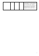
Immobilisation Circuits. (Starter Motor & Fuel Pump). The starter wire is usually
located under the steering column of the vehicle. This wire must be +12 Volts
only when the vehicle is being started. Cut this wire. The vehicle should not start.
Solder the starter motor side to one of the blue wires. Solder the other end to
the other blue wire. Repeat this configuration for the electric fuel pump. Under no
circumstances should you cut the vehicle’s main ignition system.
WHITE/YELLOW
-
Negative on Arm (200mA Max). Connect to the negative wire (usually black) on
any accessory used ie. ultrasonic or microwave detectors. Also used to trigger
electric window lift modules.
PINK
-
Connect to existing door switches. Please note: only negative switching doors, if
positive door switching - must use relays to reverse to negative - see diagram
contained later in this manual)
VIOLET
-
Bonnet Switch Negative Input. Connect to bonnet switch supplied.
WHITE/RED
-
Negative Boot Release Output (200mA Max). Please refer to the illustrated
diagram for connection details. Additional 40A Changeover Relay Required.
ORANGE
-
Negative Out on Alarm. Use to interface to pager or additional siren (200mA
maximum)
BLACK/BLUE
-
Unlock NC. Refer to diagrams contained later in this manual for central locking
connection .
GREEN/YELLOW
-
Unlock COM. Refer to diagrams contained later in this manual for central locking
connection .
RED/BLUE
-
Unlock NO. Refer to diagrams contained later in this manual for central locking
connection .
BLUE/YELLOW
-
Lock NC. Refer to dia
g
rams contained later in this manual for central lockin
g
Main Module
Blue
Blue
Fuel
Pump
Blue
Blue
Starter
Wire
7