Model: RAMV2 Designed in Australia by Instruction Manual Automotive Security System with 2-Way GSM Communication Via SMS Messaging Version 7.1 Document:RamV7.
Contents Contents......................................................................................................................... 2 Quick Reference Guide ................................................................................................. 4 1. Introduction ............................................................................................................... 5 1.1. Mobile Features................................................................................................
3. Programming & Setup .............................................................................................23 3.1. Learning New Remotes.....................................................................................23 3.1.1. Learn a new Remote Control By SMS ......................................................23 3.1.2. Learn a new Remote Control with Remote ............................................24 3.2. Programming PIN Numbers .........................................................
Quick Reference Guide STEPS TO QUICKLY SETUP THE RAM 1. Setup the SIM card for operation in the system. (ref. 2.5. SIM Card Setup And Functionality – Page: 14) 2. Setup the PIN Number. (ref. 3.4.4. To Change Your PIN Number – Page: 29) 3. Setup the Identification of the alarm system. This ‘Identification’ is a description for the system that appears at the start of every SMS message you will receive from the alarm system. (ref. 3.4.5 To Change The ID Of The SMS message – Page: 30) 4.
1. Introduction As Australia's leading designer & manufacturer of quality car security systems we are proud to release our latest model that enables 2-way communication between you and your vehicle via your mobile phone. The RhinoCo model RAM is based on our Australian Standards Approved and Insurance Approved RA “Split System” including Two Point Engine Immobilisation, Backup Battery, Black Wiring Harness, Glass Break Sensor, Selectable Passive Arming, and the advanced PRE-ALERT car body impact sensors.
1.2.
1.4. What You Get Below is a list of parts included with system. Item Description 1. Main control unit This All-In-One unit incorporates the mobile phone engine, the SIM card holder, and the main security alarm electronics module. The main wiring harness plugs into the main control unit securely via the 24 way connector. . 2. 1 Back Up Battery Siren This high frequency siren generates an intolerable noise to the human ear, and is designed to help repel intruders from your vehicle.
1.5. Mobile Phone Unit Safety Precautions Important notes about on-board GSM phones. 1.5.1. Aircraft Safety Mobile phones can interfere with an aircraft’s navigation system and its mobile network. The use of the Mobile Phone Units on board aircraft is forbidden by law and should be switched off. 1.5.2. Electronics in Medical Equipment Radio transmitters, including mobile phones can interfere with the operation of inadequately protected medical devices.
2. Installation & Operation 2.1. Planning the Installation Each separate component of the RAM should be placed in strategic locations. Below is a guide to where you should locate the main unit, the phone antenna & the siren. It is important to remember that the GSM antenna must be located high, but just underneath the centre of the dashboard out of sight. An external antenna is not used for security purposes.
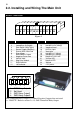
2.2. Installing and Wiring The Main Unit Harness Connections 1 2 3 4 5 6 7 8 9 10 11 12 13 14 15 16 17 18 19 20 21 22 23 24 Figure 2 PIN No 1 2 3 4 5 6 7 8 9 10 11 12 1 CONNECTION Immobiliser 2a (8Amp) Immobiliser 2b (8Amp) Door Switch (Neg Types) Bonnet Trigger (Neg Sw.) Dummy Wire, Not used.
2.2.1. Extended Wiring Descriptions PIN No CONNECTION 1,14 & 2,13 Locate the positive feed wire to the fuel pump, cut that wire and join each pair of wires from pins (1,14) & (2,13) to either end of the fuel pump feed wire which you have just cut WARNING: The Internal cut out relays have an 8 AMP maximum rating. Disable only starter solenoid, fuel pump, or ignition coil if the vehicle is not EFI. UNDER NO CIRCUMSTANCES SHOULD YOU CUT THE VEHICLE’S MAIN IGNITION SYSTEM.
2.2.2. Installing the Glass Break Microphone The glass break microphone is permanently attached to the RAM via a 1-metre length of shielded audio wire. This wire must not be cut or modified in any way. The microphone must be mounted on the front of the dashboard. Be sure to mount the microphone in a place where it will not be bumped or damaged from persons in the vehicle. There is a clip attached to microphone to assist in mounting the microphone to the front of the dashboard.
Wiring the Siren +12V: Connect to constant 12V GND: Connect to Earth *SIREN: Connect to siren wire on RAM (pin 6) * This wire is normally earthed and goes open circuit to trigger the siren - Before connecting each wire, the identification label on the end of each wire should be cut off. Back up battery test After the installation is complete, switch the siren to the on position. The siren will beep once if the backup battery is OK and 5 times if the back-up battery is flat.
2.4. Installing The Antenna Installing the GSM Antenna The phone Antenna is connected to the main unit by plugging in the antenna into the back of the RAM unit as shown in Figure 4. Figure 4 2.5. Sim Card Setup And Functionality Place the new SIM card in an existing mobile phone and deactivate (turn off) “pin code request.” You may need to refer to your mobile phone manual on how to do this. Insert the SIM card into the RAM.
2.6. Accessibility Note To prevent unauthorised access to the alarm, the user is required to ALWAYS put the 6 Digit PIN (consisting of 0-9, A-Z) (the Default Pin Number is – 000000) at the start of each SMS command to confirm the user has access to change the alarm condition (this is nothing to do with the SIM card PIN number) i.e. Arm, Disarm, Activating relays etc. If the PIN number is forgotten, please refer to section 3.4.4. To Change Your Pin Number – Page: 30. 2.7.
2.8. SMS Command Messages Refer to your mobile phones user manual on how to write SMS messages. 2.8.1. To Arm The Alarm NOTE: From the siren you will hear: 1 Beep for Normal Arming 3 Beeps for No Coverage warning Constant Beeps for 3 seconds for Door Ajar warning BY SMS ARM: Type your PIN number and ARM from a mobile phone, and send it to the alarm. 123456ARM or 123456A BY REMOTE CONTROL Pressing the Bottom button on the remote control arms the alarm.
2.8.2. To Dis-Arm The Alarm BY SMS BY REMOTE CONTROL DISARM: Type your PIN number and DISARM from a mobile phone, and send it to the alarm. To disarm the alarm, press the Bottom button again. The blinkers will flash twice and the siren will beep twice. THE ALARM IS NOW OFF. 123456DISARM 123456DISARM OR or 123456D 123456D (WHERE 123456 = YOUR PIN NUMBER) NOTE: For the DISARM command you can use the letter ‘D’ instead of ‘DISARM’.
2.8.3. Emergency Panic BY SMS PANIC: Type your PIN number and PANIC from a mobile phone, and send it to the alarm. Once the message is sent the alarm will go into “PANIC ALERT.” This will sets off the siren and sends an SMS message to ALL phone numbers alerting them that panic is activated. BY REMOTE CONTROL To SET the alarm into “PANIC mode”, press the Right button. This will sets off the siren & blinkers, and sends an SMS message to all phone numbers alerting them that the alarm is in “PANIC ALERT.
2.8.5. Car Battery Low Warning The system will send you an SMS when your car battery voltage reaches a critical level i.e. if you leave your lights on & drain your battery. The message sent is “Battery Low Warning”. The message will only be sent BATTERY BatteryLOW once in a low battery condition. WARNING! low warning! This message will be sent to all mobile phone numbers programmed into the RAM. 2.8.6. Boot Release The alarm is fitted with remote boot release capability.
2.8.8. Auto Bypass Auto bypass is designed to reduce false alarms caused by faulty switches or external sensors. If the alarm is triggered 3 times by the same sector then the particular sector will be bypassed. (i.e. The sector will become inactive.) The sector will only be bypassed for one arming period. The next time the system is armed the sector that was bypassed will become active again. 2.8.9.
2.8.13. Pre-Alert Impact Warning With ETS TM This special feature provides a two-stage impact sensing system. It gives the security conscious owner a sensitive car body impact sensor that will give a potential thief prior warning that the vehicle is protected by this most formidable alarm system. On detection of a low level impact i.e. from a tyre kick, the siren will simply beep for a few seconds to warn away the would-be thief.
2.8.15. PAT TM – Past Alarm Trigger Memory/History REMOTE CONTROL To identify the cause of the last TEN reasons why the alarm has triggered, you can follow the steps described in Section 3.3.3. Changing Register 3 – Page: 28. Or type your PIN number and HISTORY from a mobile phone, and send it to the alarm. Once the message is sent the alarm you will receive an SMS back saying ALARM HISTORY: Oldest XXX. XXX. XXX. XXX. … Latest (where XXX is the cause of the alarm being triggered) 2.8.16.
3. Programming & Setup 3.1. Learning New Remotes 3.1.1. Learn a new Remote Control By SMS SMS - To add remotes if all remotes are lost a combination of SMS and beeps can add a new remote. A. Send the command “LEARN” You will receive a SMS saying: If you receive a SMS saying “Unable to activate learn mode Ignition on” or “Unable to activate learn mode System Armed” Disarm the alarm and turn the ignition to the off position and repeat step ‘A’ again. B.
3.1.2. Learn a new Remote Control with Remote To add a new transmitter to your alarm, simply follow the procedure below: A. Turn the vehicle’s ignition on. B. Immediately press and hold the Bottom button on the Original remote control until the siren starts to beep (approximately 4 seconds) and then release the button. C. Immediately press and hold the same (Bottom) button on the New remote control for at least 4 seconds. D. Turn the vehicle’s ignition off. E.
3.2. Programming PIN Numbers NEWPIN – In the case of loosing your PIN number for the RAM alarm system. Simply send a message to your alarm: NEWPINXXXXXX – where XXXXXX is the new pin number you want to have consisting of 0-9, a-Z. (Not case sensitive) NEWPIN123456 NEWPIN123456 When you send the message and the unit has received it the siren will start beeping 9 times and the indicators will flash.
3.3. Remote Control Programmable Features Your Rhino Security system incorporates the latest in high security features. It is possible to customise your security system so that it suits your requirements perfectly. Detailed below is the full list of programmable features that can either be turned on or turned off. We have set at the factory the most common configuration chosen and these settings are listed in the REGISTER Settings listed below.
3.3.1. Changing REGISTER 1 Vehicle Set Up: ALL DOORS CLOSED, BONNET CLOSED, AND THE IGNITION TURNED ON LAST Remote Key action : TURN ON / OFF FEATURES VIA THE BOTTOM BUTTON ON THE REMOTE Press INITIAL DESCRIPTION PROGRAMMABLE Remote FACTOR FEATURE This Y Many SETTIN G Times Arming Beep 1 ON 1 Beep on Arm Disarm Beep 2 ON 2 Beeps on Disarm Auxiliary Detection 3 ON Activate Ultrasonics, Microwave if fitted. Shock Sensor 4 ON Activate Two Stage Shock Sensor.
3.3.2. Changing REGISTER 2 Vehicle Set Up: DRIVER’S DOOR OPEN, BONNET CLOSED, AND THE IGNITION TURNED ON LAST Remote Key action : TURN ON / OFF FEATURES VIA THE BOTTOM BUTTON ON THE REMOTE PROGRAMMABLE Press INITIAL DESCRIPTION FEATURE Remote FACTORY This Many SETTING Times Left Button Used For 1 OFF Allows your remote keys to be divided to act like two Another Vehicle separate single button remote keys to control two separate vehicles, i.e.
3.3.3.
3.4. Phone Number Memory The Rhino RAM alarm is able to be programmed with up to 5 different mobile phones, so when the alarm is armed or put in to panic mode and activates it will send a SMS message to each of the phone numbers in the systems memory. 3.4.1. To Read Phone Numbers From The System BY SMS ONLY Type your PIN number and READPHONE, and send it to your alarm you can find out the different mobile numbers that are programmed into the system.
3.4.3. To Add Phone Numbers To The System BY SMS ONLY By typing your 6 digit PIN number and WRITEPHONEXYYYY from a mobile phone, you can add a mobile phone number to the alarm system. The mobile phone number ‘YYYY’ will go in location ‘X’. (X must be between 1 – 5 ) PIN NUMBER 123456 123456 WRITEPHONEXYYYY WRITEPHONEXYYYY LOCATION: 1 to 5 ⇓ ⇓ EG: 123456 WRITEPHONE 3 0409986655 ⇑ ⇑ COMMAND NEW PHONE NUMBER will add the phone number 0409986655 to location 3 in the alarm.
3.4.5. To Change The ID Of The System BY SMS ONLY You can change the ID Message that is displayed at the start of the SMS messages you receive. Where XXXXXX is a code to distinguish the alarm from another system. i.e. The car’s rego number. Up to 19 characters can be used for the ID. You will then receive a reply SMS message back saying: ABC123. ID change passed. 123456IDXXXX 123456IDXXXXX ABC123: ABC123: ID CHANGE PASSED. ID CHANGE PASSED. EG: 123456IDABC123 – will change the current ID to ABC123.
4. Warranty 4.1. Warning Limitations & Warranty While this system is an advanced security system, it does not offer guaranteed protection against burglary or any other emergency. Any alarm system, whether commercial or residential, is subject to compromise or failure to warn for a variety of reasons. For example: • Intruders may gain access through unprotected openings, or have the technical sophistication to bypass an alarm or disconnect an alarm warning device. • Intrusion detectors (e.g.
LIMITED WARRANTY Cornick Pty Ltd (ABN 74 001 621 610) (Seller), warrants its products to be in conformance with its own plans and specifications and to be free from defects in materials and workmanship under normal use and service for twelve months from the date of original purchase.
5. SMS Commands Reference 1. Not case sensitive i.e. 000000DiSaRm (the software converts it all to uppercase internally) 2. Limit to SMS is 25 messages in 8.5 minutes (the system automatically overrides the sending of to many messages) 3. Default pin code is 000000 (all zero’s) 4. Messages that contain no valid PIN code that are sent to the RAM will not get responded to (ref NEWPIN) 5.
>WRITEPHONExyyyyyyy (phone memory location x = (1-5) with phone number = y ) >WRITEPHONE30414221331 (example) IDxxxxx (write rego or other message to be at the start of every message received from RAM =< 19 characters) < xxxxxx. ID change passed. i.e. 123456IDXBU-458 replies with XBU-458. ID change passed.
This page intentionally blank.
This page intentionally blank.
This page intentionally blank.