WHEEL RAKES Published 11/04 4782C OPERATOR'S MANUAL This Operator's Manual is an integral part of the safe operation of this machine and must be maintained with the unit at all times. READ, UNDERSTAND, and FOLLOW the Safety and Operation Instructions contained in this manual before operating the equipment. WHEEL RAKE/V-RAKE MODELS (2, 4, 6, 8, & 10 WHEEL MODELS) M&W 1020 South Sangamon Ave. Gibson City, Illinois 60936 217-784-4261 An Alamo Group Company © 2004 Alamo Group Inc.
TO THE OWNER/OPERATOR/DEALER All implements with moving parts are potentially hazardous. There is no substitute for a cautious, safe-minded operator who recognizes the potential hazards and follows reasonable safety practices. The manufacturer has designed this implement to be used with all its safety equipment properly attached to minimize the chance of accidents. BEFORE YOU START! Read the safety messages on the implement and shown in your manual.
BE SAFE! BE ALERT! BE ALIVE! BE TRAINED before operating the Mower! Safety Training Makes the Difference In order to reduce accidents and enhance the safe operation of mowers, Alamo Group Ag Division, in cooperation with other industry manufacturers has developed the AEM/FEMA Industrial and Agricultural Mower Safety Practices video and guide book. The video will familiarize and instruct mower-tractor operators in safe practices when using industrial and agricultural mowing equipment.
Alamo Group Ag.
TABLE OF CONTENTS Specifications ............................................................................................................................................... 2 Safety Instructions ........................................................................................................................................ 2 Assembly ......................................................................................................................................................
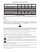
3-POINT WHEEL RAKE SPECIFICATIONS Model Weight (Lbs.
SAFETY A safe and careful operator is the best operator. Safety is of primary importance to the manufacturer and should be to the owner/operator. Most accidents can be avoided by being aware of your equipment, your surroundings, and observing certain precautions. The first section of this manual includes a list of Safety Messages that, if followed, will help protect the operator and bystanders from injury or death.
SAFETY READ, UNDERSTAND, and FOLLOW the following Safety Messages. Serious injury or death may occur unless care is taken to follow the warnings and instructions stated in the Safety Messages. Always use good common sense to avoid hazards. (SG-2) PELIGRO! Si no lee Ingles, pida ayuda a alguien que si lo lea para que le traduzca las medidas de seguridad.
SAFETY DANGER! Never allow children to operate or ride on the Tractor or Implement. (SG-11) WARNING! Do not mount the Tractor while the tractor is moving. Mount the Tractor only when the Tractor and all moving parts are completely stopped. (SG-12) DANGER! Start tractor only when properly seated in the Tractor seat. Starting a tractor in gear can result in injury or death. Read the Tractor operators manual for proper starting instructions.
SAFETY CAUTION! PROLONGED EXPOSURE TO LOUD NOISE MAY CAUSE PERMANENT HEARING LOSS! Tractors with or without an Implement attached can often be noisy enough to cause permanent hearing loss. We recommend that you always wear hearing protection if the noise in the Operator’s position exceeds 80db. Noise over 85db over an extended period of time will cause severe hearing loss. Noise over 90db adjacent to the Operator over an extended period of time will cause permanent or total hearing loss.
SAFETY WARNING! Periodically inspect all moving parts for wear and replace when necessary with authorized service parts. Look for loose fasteners, worn or broken parts, and leaky or loose fittings. Make sure all pins have cotter pins and washers. Serious injury may occur from not maintaining this machine in good working order. (SG-21) DANGER! Never run the tractor engine or mower engine in a closed building or without adequate ventilation. The exhaust fumes can be hazardous to your health.
SAFETY WARNING! Be particularly careful when transporting the Implement with the Tractor. Turn curves or go up hills only at a low speed and using a gradual steering angle. Rear mounted implements move the center of gravity to the rear and remove weight from the front wheels. Make certain, by adding front ballast, that at least 20% of the tractor’s weight is on the front wheels to prevent rearing up, loss of steering control or Tractor tip-over.
SAFETY WARNING! Never unhitch without using the Tongue Jack. The Tongue is very heavy. Attempting to lift the Tongue without using the Tongue Jack could cause strains or other injury. Allowing the tongue to fall suddenly and unexpectedly could result in crushing injury. Use the Tongue Jack for lifting the mower only. Overloading the Tongue Jack can cause failure with possible serious bodily injury or even death.
ASSEMBLY Your M&W Rake may come unassembled or partially assembled as required using the following instructions. 1. Install the Sector Support (8) on the 3-Point Base (1). Insert the 3-Point Cap (17) and secure in place with a capscrew and locknut through the cap and base. Lock the support plate in position on the 3-point base with a 3-point pin (10) secured with a Hairpin Cotter (9). See Illustration 1. Illustration 1 Illustration 2 2.
5. Insert the Main Frame (33) into the Floating Arm (26). Lock the in place by installing the Lever Plate (16) on the floating arm and secure with a pin and retaining rings. Insert a Lever Plate Pin (19) to lock the stop plate and secure with a hairpin cotter. See Illustration 3. Illustration 4 Illustration 3 6. Install the wheel Arms (34) in the main frame and secure the Lever Plates (16) with a pin and retaining rings and a lever pin secured with a hairpin cotter .
CONNECTING THE RAKE TO THE TRACTOR With the rake supported by the wheel teeth and the stand, back the tractor to the rake and connect the tractor to the 3-point linkage. After connecting to the tractor raise the machine and remove the stand from the 3-point linkage. Raise the rake guard using the tractor hydraulics until the teeth are off of the ground. Slide the Lock Plate (27) to the rear "B" to allow the rake to "float" during operation. (See Illustration 7).
WORKING POSITIONS Pull the pin in the sector support and turn the main frame to the right and rotate the arms so the wheels are positioned as shown below (See Illustration 10). During operation, the wide slots in the frame and arm flanges allow the arms to oscillate slightly to prevent damage to teeth by rough ground surfaces. The narrow slots used in the transport positioning hold the arms in a rigid position.
USING LEFT AND RIGHT-HAND MODELS TO MAKE A V-RAKE 1. Install the Tool Bar Frame (1) to the tractor 3-point linkage using a forklift or crane. Raise the frame with tractor's hydraulics. (See Illustration 13). 2. Install the 3-Point Upper and Lower Linkage (9 & 11) on the frame. Do not tighten bolts until all components are in place and rakes are installed so minor adjustments can be made. 3. Install the assembled left and right rakes to the toolbar frame.
TROUBLESHOOTING PROBLEM PROBABLE CAUSE SOLUTION Hay carrying over on the wheels. Teeth not polished. Operate rake on gravel surface for a short distance. Mud collected on tine ends. Dew on hay, wait until dry. Do not run in soft, wet ground. Tooth Breakage. Backing with teeth in contact with ground. Avoid backing with teeth on ground. Too much of rake weight on wheels. Corrosion in storage. Rake missing hay. Wheels running too fast. Raise the 3-point hitch slightly.
M&W LIMITED WARRANTY 1. LIMITED WARRANTIES 1.01.M&W warrants for one year from the purchase date to the original non-commercial, governmental, or municipal purchaser (“Purchaser”) and warrants for six months to the original commercial or industrial purchaser (“Purchaser”) that the goods purchased are free from defects in material or workmanship. 1.02.
TO THE OWNER/OPERATOR/DEALER To keep your implement running efficiently and safely, read your manual thoroughly and follow these directions and the Safety Messages in this Manual. The Table of Contents clearly identifies each section where you can easily find the information you need. The OCCUPATIONAL SAFETY AND HEALTH ACT (1928.51 Subpart C) makes these minimum safety requirements of tractor operators: REQUIRED OF THE OWNER: 1. 2. 3. 4.
Printed U.S.A.
An Alamo Group Company M&W® 1020 S. Sangamon Ave. Gibson City, IL 60936-9907 Please fold (do not tear), tape, and drop in any mailbox. PLEASE FILL OUT OWNER WARRANTY REGISTRATION INFORMATION SIGN, AND DROP LAST COPY IN ANY MAILBOX. IMPORTANT! TO PLACE THIS WARRANTY IN EFFECT, THIS WARRANTY REGISTRATION MUST BE FILLED OUT, SIGNED, AND MAILED WITHIN 30 DAYS OF DELIVERY DATE OF THIS MACHINE. DEALER AND PURCHASER MUST SIGN.
M&W WARRANTY REGISTRATION INFORMATION MONTH Serial No. M&W Model DAY YEAR Purchase Date Purchaser Last Name Street & No., RFD, Box, &/or Apt. No. First Name City M.I.
2. REMOVE WHITE COPY FOR CUSTOMER RECORDS. 3. REMOVE YELLOW COPY FOR DEALERS RECORDS. 4. MAIL LAST CARD POSTAGE FREE. M&W® WARRANTY REGISTRATION INFORMATION MONTH Serial No. M&W Model Purchaser Last Name Street & No., RFD, Box, &/or Apt. No. City DAY YEAR Purchase Date First Name M.I.
2. REMOVE WHITE COPY FOR CUSTOMER RECORDS. 3. REMOVE YELLOW COPY FOR DEALERS RECORDS. 4. MAIL LAST CARD POSTAGE FREE. M&W® WARRANTY REGISTRATION INFORMATION MONTH Serial No. M&W Model Purchaser Last Name Street & No., RFD, Box, &/or Apt. No. City DAY YEAR Purchase Date First Name M.I.