
User's Manual


Direction Finder RHOTHETA RT-400
RHOTHETA Page 12 of 18 User Manual
8 Service and Maintenance of the RT-400 Power Pack
8.1 Installation of the Power Pack
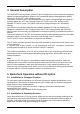
The power pack can be plugged into, and removed from, the power pack rack of the carrying
frame.
The power pack must be plugged into its rack as shown in the pictures above. As soon as the
power pack is locked by the locking spring, it is automatically connected to the backward
connector on the carrying frame and ready for use.
To remove the power pack, pull the locking spring and unplug the power pack by pulling it
forward.
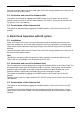
8.2 Battery / Accumulator Replacement and Protection
The Power Pack operates with an internal 14,4 V NiMH accumulator package.
Use a Torx (size TX10) screw driver to remove the two screws on the back side of the Power
Pack. The whole Battery Pack board can be removed from the housing and the accumulator
may be replaced.
All input- and output connections are fused: Charge Input (CHARGE, 4 A slow-blow), Antenna
Unit Output (AU, 1 A slow-blow) and Lift Output (LIFT, 0,5 A slow-blow).
Additionally, spare fuses are provided.