
Specifications
Tools
INITIAL SETUP
TM 9-2350-311-34-1
SECTION I. UNIVERSAL JOINTS AND COOLING FAN DRIVE ASSEMBLY
6-1 UNIVERSAL JOINTS
This task covers:
a. Removal
b. Inspection
c. Installation
General mechanic’s tool kit (item 14, Appx C)
Vernier calipers (item 2, Appx C)
a. Removal
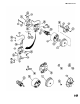
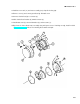
1
Push two sleeve joints (1 and 2) downward and remove from splined shafts (3 and 4) on fan gearboxes (5 and
6).
2 Pull two universal joints (7 and 8) away from cooling fan drive (9) and up through opening in shroud (10).
b. Inspection
1
2
3
4
5
6
7
8
NOTE
If any item is found defective during inspection, entire universal joint must be
replaced.
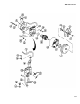
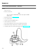
Check end hubs (11) for chipped, broken, or missing splines (12).
Measure shaft length of universal joint (8) under static no-load condition. Length should not exceed 14.5 in.
(36.8 cm).
Apply 20 lb (9.1 kg) and 2 lb (0.9 kg) compression to universal joint (8).
Measure shaft length of universal joint (8) under compression. Length should be no less than 13.2 in. (33.5
cm).
Check end hubs (11) for chipped, broken, or missing splines (12).
Measure shaft length of universal joint (7) under static no-load condition. Length should not exceed 12 in. (30.5
cm).
Apply 20 lb (9.1 kg) and 2 lb (0.9 kg) compression on universal joint (7).
Measure shaft length of universal joint (7) under compression. Length should be no less than 10.7 in. (27.2
cm).
6-2