
Specifications


Tools
References
Equipment Conditions
Materials/Parts
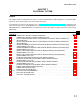
INITIAL SETUP
CAUTION
TM 9-2350-311-34-1
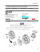
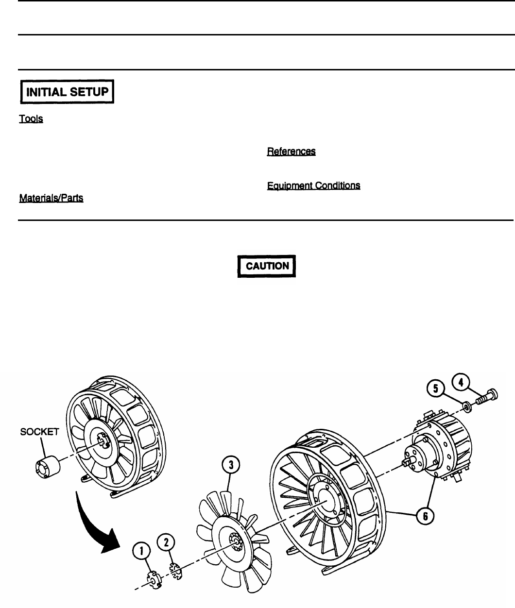
6-4 VANEAXIAL COOLING FANS AND FAN DRIVE GEARBOX
This task covers:
a. Disassembly
b. Inspection and Test
c. Assembly
Seal (item 66, Appx F)
General mechanic’s tool kit (item 14, A
PPX
C)
Seal (item 67, Appx F)
Dial indicator (item 4, Appx C)
Fabricated measuring bar (item 5, A
PPX
D)
Socket (item 19, Appx C)
TM 9-2350-311 -20-1
Toque wrench (item 28, Appx C)
Cooling fans removed from shroud (para 6-3)
Key washer (item 7, Appx F)
a. Disassembly
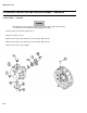
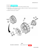
Use extreme care when removing impeller to avoid any damage. If impeller is
damaged, entire vaneaxial fan assembly must be replaced.
1 Remove nut (1) using socket and remove key washer (2) and impeller (3). Discard key washer.
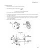
2 Remove 10 socket head screws (4), 10 washers (5), and gearbox assembly (6).
6-13