
Specifications


TM 9-2350-311-34-1
SECTION Il. TRACK SUSPENSION
8-2 ROAD WHEEL ARM ASSEMBLY — UPPER SPINDLE
This task covers: a. Disassembly
b. Assembly
Seal (item 61, Appx F)
General mechanic’s tool kit (item 14, Appx C)
Seal (item 71, Appx F)
Prong wrench (item 25, Appx C)
Torque wrench (item 26, Appx C)
TM 9-2350-311-20-1
Grease (item 9, Appx B)
t Conditions
.
Key washer (item 8, Appx F) Road wheel arm assembly removed (TM 9-2350-311-20-1)
Preformed packing (item 21, Appx F)
a. Disassembly
1
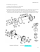
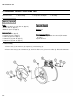
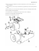
Remove two screws (1), housing (2), preformed packing (3), and seal (4). Discard preformed packing and seal.
2 Straighten key washer (5) tabs.
3 Remove nut (6) using prong wrench.
4 Remove key washer
5 Remove retainer (9),
b. Assembly
1
2
3
4
5
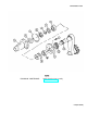
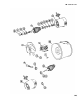
Apply coat of grease
Install new seal (12),
(5), thrust spacer (7), and inner bearing race assembly (8). Discard key washer.
outer bearing race assembly (10), bearing spacer (11), and seal (12). Discard seal.
to mating surface of new seal (12).
retainer (9), outer bearing race assembly (10), bearing spacer (11), inner bearing race
assembly (8), thrust spacer (7), and new key washer (5) to upper spindle (13).
Install nut (6) to upper spindle (13) using prong wrench. Torque nut to 255-275 Ib-ft (346-373 N-m).
Bend key washer (5) tabs to secure key washer to nut (6).
Install new seal (4), new preformed packing (3), housing (2), and two screws (1).
8-6