® Benchmark LP Low-Profile Bench Scale Installation Manual 104742 Rev A
Contents 1.0 Introduction..................................................................................................................................... 1 1.1 Safety . . . . . . . . . . . . . . . . . . . . . . . . . . . . . . . . . . . . . . . . . . . . . . . . . . . . . . . . . . . . . . . . . . . . . . . . . 2 2.0 Installation ...................................................................................................................................... 3 2.1 2.2 2.3 2.4 3.
Rice Lake continually offers web-based video training on a growing selection of product-related topics at no cost. Visit www.ricelake.com/webinars.
1.0 Introduction The CubeLogic 250 is a four-cell, low-profile scale. Features include: • Available in sizes from 18 in. x 18 in (.46 m x 46 m) to 36 in x 36 in (.91 m x .91 m). • Capacities from 100 to 1000 lbs (45 - 453 kg). • Fully electronic low-profile load receivers. • Four corner-mounted, FM-approved planar beam load cells. • Signal-trim summing board for any necessary corner corrections, mounted under a stainless steel cover that can be sealed for legal-for-trade.
1.1 Safety Safety Symbol Definitions: Indicates a potentially hazardous situation that, if not avoided could result in death or serious injury, and WARNING includes hazards that are exposed when guards are removed. Indicates information about procedures that, if not observed, could result in damage to equipment or Important corruption to and loss of data. General Safety Do not operate or work on this equipment unless you have read and understand the instructions and warnings in this manual.
2.0 Installation Standard installation of the Benchmark™ LP floor scale consists of the following steps: • Select a site • Check levelness and smoothness of site • Unpack scale • Adjust the four feet on the scale • Connect cable to summing board and indicator • Calibrate the unit 2.1 Site Preparation The scale must not be loaded beyond its capacity, even momentarily. Do not select a site where overweight loads would have to maneuver to avoid crossing the platform.
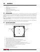
2.3 Summing Board Security After an NTEP inspector has examined the unit, he/she will install security cables on the summing board cover. These cables prevent the summing board from being tampered with by an unauthorized individual. If these cables are removed, NTEP Certification will become void. Figure 2-2. Summing board cover with security cables installed 2.4 Electrical Interface to Indicator Twenty feet of 6-wire cable to connect the scale to the weight indicator is supplied with each scale.
Cable Routing The cable must be routed to the indicator in a manner that will protect the cable from damage. When planning cable routing, leave a loose coil of excess cable under the scale to facilitate future lifting of the scale for servicing or cleaning. 1. When the interface cable is protected and in its final position, complete connections to the indicator. See indicator installation manual for wiring information. 2. If necessary, trim corners as described in Section 3.2 on page 6. 3.
3.0 3.1 Adjustments and Calibration Mechanical Adjustments To accommodate minor floor unevenness, scale feet can be used to adjust scale height up or down a fraction of an inch. Adjust the feet by hand (lift the scale corner slightly with a pry bar) until all feet are contacting the floor equally. Jam nuts are supplied for locking the feet in place. When height adjustments are complete, recheck level of the deck with a spirit level. The deck must be level within 1 /4". 3.
3.3 Calibration Procedure Refer to the indicator manual to determine correct calibration procedures. It is recommended that the scale be "exercised" before calibration to be certain that everything is seated. 1. Load the scale to near capacity two or three times. 2. With no load on the scale, place the indicator in its calibration mode and perform a zero calibration. 3. Place test weights on the platform not exceeding the scale's full capacity.
4.0 4.1 Service Information Troubleshooting Guide System does not operate—no display • Power disconnected: Check and reconnect. • Indicator fuse blown. Replace fuse. Check for cause. • Interface cable cut or disconnected: Repair.
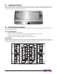
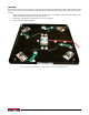
4.3 Load Cell Replacement Replacement load cells can be ordered from Rice Lake Weighing Systems according to the part numbers in Table 4-2 on page 10. Refer to Table 1-1 on page 1 for torque settings. 1. Remove defective load cells. 2. Disconnect load cell cable from summing board and cut cable ties. 2 3 1 4 Figure 4-1. Load Cell Arrangement 3. When the cable is freed, pull cable out of the scale. 4. Lay out each load cell near the corner where it is to be installed. 5.
4.3.1 Load Cell Wiring to Summing Board The four load cells are each wired to their respective terminals in the summing board according to the corner numbering system shown in Figure 4-3 and the coloring code in Table 4-1. Hole for homerun cable 3 4 2 1 Figure 4-3. Corner numbering (top view) Cable Color Code Summing Board Terminal Green + Excitation Black - Excitation White + Signal Red - Signal Table 4-1. Load Cell Wiring 4.
Benchmark LP Limited Warranty Rice Lake Weighing Systems (RLWS) warrants that all RLWS equipment and systems properly installed by a Distributor or Original Equipment Manufacturer (OEM) will operate per written specifications as confirmed by the Distributor/OEM and accepted by RLWS. All systems and components are warranted against defects in materials and workmanship for two years. RLWS warrants that the equipment sold hereunder will conform to the current written specifications authorized by RLWS.
12 Benchmark Series Low-Profile Bench Scale
230 W. Coleman St. • Rice Lake, WI 54868 • USA U.S. 800-472-6703 • Canada/Mexico 800-321-6703 • International 715-234-9171 • Europe +31 (0)26 472 1319 www.ricelake.com www.ricelake.mx www.ricelake.eu www.ricelake.co.in m.ricelake.