Benchmark LP TM Low-Profile Bench Scale Installation Manual 104742
Contents Contents ................................................................................................................................................... i About This Manual ................................................................................................................................... 1 1.0 Introduction.................................................................................................................................. 1 2.0 Installation .........................
ii Benchmark LP Manual
About This Manual This manual is intended for use by service technicians responsible for installing and servicing the Benchmark™ LP low-profile bench scale. Warning 1.0 Authorized distributors and their employees can view or download this manual from the Rice Lake Weighing Systems distributor site at www.ricelake.com. Some procedures described in this manual require work inside the summing board enclosure. These procedures are to be performed by qualified service personnel only.
2.0 Installation Standard installation of the Benchmark™ LP floor scale consists of the following steps: • Select a site • Adjust the four feet on the scale • Check levelness and smoothness of site • Connect cable to summing board and indicator • Unpack scale • Calibrate the unit 2.1 Site Preparation The scale must not be loaded beyond its capacity, even momentarily. Do not select a site where overweight loads would have to maneuver to avoid crossing the platform.
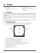
2.3 Summing Board Security After an NTEP inspector has examined the unit, he/she will install security cables on the summing board cover. These cables prevent the summing board from being tampered with by an unauthorized individual. If these cables are removed, NTEP Certification will become void. Figure 2-2. Summing board cover with security cables installed 2.4 Electrical Interface to Indicator Twenty feet of 6-wire cable to connect the scale to the weight indicator is supplied with each scale.
Cable Routing The cable must be routed to the indicator in a manner that will protect the cable from damage. When planning cable routing, leave a loose coil of excess cable under the scale to facilitate future lifting of the scale for servicing or cleaning. 1. When the interface cable is protected and in its final position, complete connections to the indicator. See indicator installation manual for wiring information. 2. If necessary, trim corners as described in Section 3.2 on page 5. 3.
3.0 3.1 Adjustments and Calibration Mechanical Adjustments To accommodate minor floor unevenness, scale feet can be used to adjust scale height up or down a fraction of an inch. Adjust the feet by hand (lift the scale corner slightly with a pry bar) until all feet are contacting the floor equally. Jam nuts are supplied for locking the feet in place. When height adjustments are complete, recheck level of the deck with a spirit level. The deck must be level within 1/4". 3.
3.3 Calibration Procedure Refer to the indicator manual to determine correct calibration procedures. It is recommended that the scale be "exercised" before calibration to be certain that everything is seated. 1. Load the scale to near capacity two or three times. 2. With no load on the scale, place the indicator in its calibration mode and perform a zero calibration. 3. Place test weights on the platform not exceeding the scale's full capacity.
4.0 4.1 Service Information Troubleshooting Guide System does not operate—no display • Power disconnected: Check and reconnect. • Indicator fuse blown. Replace fuse. Check for cause. • Interface cable cut or disconnected: Repair.
7. Position load cells with capacity label and load cell wires facing up, and loosely install the hex head cap screws (provided). 8. Route the load cell cables along the frame to the summing board. 9. Secure the cable in position with the adhesive-backed cables tied supplied in the hardware kit. See Figure 4-2 for an illustration of load cell and cable placement. Hole for homerun cable 3 4 2 1 NOTE: Do not cut load cell cables. Figure 4-3.
Benchmark LP Limited Warranty Rice Lake Weighing Systems (RLWS) warrants that all RLWS equipment and systems properly installed by a Distributor or Original Equipment Manufacturer (OEM) will operate per written specifications as confirmed by the Distributor/OEM and accepted by RLWS. All systems and components are warranted against defects in materials and workmanship for two years. RLWS warrants that the equipment sold hereunder will conform to the current written specifications authorized by RLWS.