
Installation manual


2 Benchmark LP Manual
2.0 Installation
Standard installation of the Benchmark
™
LP floor scale consists of the following steps:
• Select a site
• Check levelness and smoothness of site
• Unpack scale
• Adjust the four feet on the scale
• Connect cable to summing board and
indicat
or
• Calibrate the unit
2.1 Site Preparation
The scale must not be loaded beyond its capacity, even momentarily. Do not select a site where overweight loads
would have to maneuver to avoid crossing the platform. Avoid areas where the scale might receive damaging
side impacts from wheels or forklift tines, or shock damage from falling objects. Avoid areas where water may
damage the scale.
The interface cable between the scale and the indicator must
be protected against crushing, cutting, or moisture
damage. If the chosen site has such potential dangers, some method of protection, such as running the cable in
conduit, will be necessary.
In operation, the scale must be level
within
1
/
4
inch. Either choose a site where the floor is close to this standard
to avoid excessive shimming, or modify the floor at the chosen site to meet this standard.
2.2 Unpacking and Assembly
1. Remove all packing material and inspect scale for visible damage caused during shipment.
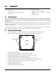
2. Remove the four overload stops on the
underside of the scale, shown in Figure 2-1.
Overload
Stops
Overload
Stops
Figure 2-1. Overload Stops to be Removed (4)
3. Remove the black scale cover.
4. Remove the summing board cover in the center of the scale.
5. Wire the homerun cable. Refer to instructions in Section 2.3 on page 3.
6. Properly secure the cable wi
th nylon ties (supplied).
7. Using the bubble level next to the summing board,
ensure the scale is level.
8. Replace the black scale cover and use the four mounting scre
ws to secure it in place.
9. If necessary, perform a corner correction. See Section 3.2 on page 5.
10. Replace the summing board cover.
11. Replace the black center cover.
12. Set the stainless steel cover on the scale.