
Installation manual


Adjustments and Calibration 5
3.0 Adjustments and Calibration
3.1 Mechanical Adjustments
To accommodate minor floor unevenness, scale feet can be used to adjust scale height up or down a fraction of an
inch. Adjust the feet by hand (lift the scale corner slightly with a pry bar) until all feet are contacting the floor
equally. Jam nuts are supplied for locking the feet in place.
When height adjustments are complete, recheck level of the deck with a spirit level. The deck must be level
within
1
/
4
".
3.2 Corner Correction
All assembled Benchmark
™
LP scales are delivered with the summing board corner-trimmed. Corner trimming is
only necessary after replacing a load cell.
To calibrate the scale, the output from each load cell
must be matched by adjusting the signals with
potentiometers at the summing board—a process known as trimming.
1. Remove the summing board cover and identify the
correct load cell terminal corresponding to each
corner (labeled CELL 1, CELL 2, and so on). See Figure 4-3 on page 8 for scale deck corner numbering.
2. The indicator must be connected and calibrated approximately
, but it need not indicate the exact weight
value. A test weight will be required. The recommended test weight for all Benchmark
™
LP models is
25% of scale capacity: for example, 25 lbs for 100-lb models, 250 lbs for 1000-lb models.
3. With no weight on the scale, zero the indicator.
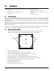
4. Turn all four potentiometers fully
clockwise (shaded areas of Figure 3-1) to increase the reading until a
clicking sound is heard from each potentiometer. This ensures the maximum signal from each load cell.
JP4
JP2
PT4
PT3
JP3
PT1
EXP
PT2
JP1
1
CELL4
1
CELL1
1
CELL3
1
CELL2
IND
-EX
-SI
SHD
+SI
+EX
M
R
N
I
-SI
S2C
I
A
G
+EX
+SI
-SI
SHD
-EX
I
S
G
A
L
T
+SI
M
S
I
N
L
T
R
+EX
-EX
-SI
SHD
+SI
+EX
+SI
-EX
-SI
SHD
-EX
SHD
+SE
-SE
+EX
Potentiometers
Jumper Locations
JP1 and JP2
Shaded
Jumper Locations
JP3 and JP4
Shaded
Potentiometers
Figure 3-1. Trim Potentiometers
5. Zero the indicator and place 25% of scale capacity using calibrated test weights over each load cell in
turn.
6. Record the value displayed on the indicator after the test weight is
placed in turn on each corner (directly
over the load cell) without allowing the weight to overhang the sides. Allow the scale to return to zero
each time to check for friction or other mechanical problems. Select the load cell which has the lowest
value as your reference point. This cell will not be trimmed.
7. Replace the same test load over each cell in turn. Using the corresponding potentiometer
, trim each cell
down to equal the reference load cell. As corner corrections are somewhat interactive, check all cells
again for repeatability. If necessary, repeat steps 5 and 6.