UMC600 Digital Weight Indicator Installation Manual 30261
Contents About This Manual ................................................................................................................................... 1 1.0 Introduction.................................................................................................................................. 1 1.1 Front Panel Keypad and Annunciators ................................................................................................ 2 2.0 Installation and Wiring .................................
4.7.3 Standard Serial Configuration................................................................................................................... 36 4.7.4 Option 7 Configuration ............................................................................................................................. 36 4.8 Option 8 – Analog Output/Relay Option ............................................................................................ 38 4.8.1 Analog Output Option Wiring............................
About This Manual This manual is intended for use by service technicians responsible for installing and servicing the UMC600 digital weight indicator. This manual provides information on installation, calibration, configuration, and operation of the UMC600. 1.0 Authorized distributors and their employees can view or download this manual from the Condec distributor site at www.4condec.com.
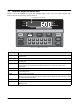
1.1 Front Panel Keypad and Annunciators Figure 1-1 shows the UMC600 front panel. The UMC600 display consist of six seven-segment display digits. Table 1-1 lists the front panel keys and their functions. Low Battery Annunicator ZERO lb NET kg MOTION GROSS CAPACITY ZERO TARE RECALL NET GROSS 5000 lb. X 0.5 lb/kg CONV TARE 1 2 3 4 5 6 7 8 9 0 CE ENT PRINT 1 SET POINT 2 SET POINT Figure 1-1. UMC600 Front Panel Panel Key Function ZERO Provides push-button auto zero (PAZ) over ±1.
Table 1-2 summarizes the front panel annunciator functions. Annunciator Function LOW BATTERY On when 12 VDC input voltage drops to approximately 11.4 VDC. ZERO On when scale weight is within ±0.25 displayed graduations of zero. Used in gross or net weighing mode. NET On when the indicator is in net weighing mode. GROSS On when the indicator is in gross weighing mode. lb/kg lb or kg LED is lit to show the current displayed weight units. MOTION On when scale is in motion.
2.0 Installation and Wiring This section describes the procedures for installing the UMC600 indicator, including connecting the load cell, digital input and serial communications cables to the indicator. Instructions for CPU board replacement are included, along with assembly drawings and parts list for the service technician. ! Caution 2.1 Use a wrist strap to ground yourself and protect components from electrostatic discharge (ESD) when working inside the indicator.
2.5 VAC Conversion 2.6 The UMC600 can be converted from 115VAC to 230VAC. The following steps are necessary to complete this conversion. Warning Before beginning, be sure to disconnect the AC power source. Failure to do so can result in injury or death. 1. Disconnect power to the indicator. Loosen cord grips and remove enclosure as described in Section 2.2 2. See Section 2.6 for CPU board removal and replacement instructions. 3.
2.7 Instrumentation Setup Notes: All indicators are configured and tested prior to shipment to ensure that they are fully functional. The unit can be turned on immediately after connecting the input power and the load cells. The UMC600 operates with the EPROM program KDA1921-1(27C512). To verify the program installed in the indicator, turn on the indicator and observe the displayed value at the EP prompt (see Figure 2-4). The EP prompt displays the family, set, and version level of the installed EPROM.
The standard connection is designed for 4-wire (non remote sensing) use. To convert to 6-wire (remote sensing) applications, cut the two PC traces on each end of TB1 as shown in Figure 2-7. Traces J5 TB1 1 2 +SIG 3 –SIG 4 –SEN 5 –EXC S3 6 LOAD CELL CONNECTOR +EXC +SEN U18 K1 J7 Check load cell color code for proper wiring. Traces J3 Q5 U2 J6 F1 GND LO HI 2 1 + Batt - TB5 TO POWER SUPPLY Figure 2-7.
2.10 Hardware Configuration Jumper pins are provided for: • • • • • EPROM chip selection Front panel switch configuration (DC on/off or batch start) Power on/off relay configuration Dual channel (optional) Time and date option (SRAM selection) These features are dependent on installed options and software. The location and jumper positions are noted in Figure 2-10.
2.11 Serial Port Wiring The UMC600 has two serial communications ports. Port 1 supports full-duplex RS-232, or 20mA current loop (active or passive), or half-duplex RS-485. Switch S1 (shown in Figure 2-12), selects the interface protocol of Port 1. Port 2 supports simplex (output only) RS-232, or 20mA current loop (active or passive). Access to the serial communication ports is through the cord grips (TB2 and TB4) located on the back of the enclosure (see Figure 2-11).
2.11.1 Serial Port #1 Wiring: CPU KGR8924–1 3 2 1 1 5 6 4 10 9 8 7 Serial Port 1 supports full-duplex RS-232, or 20mA current loop (active or passive), or half-duplex RS-485. Switch S1 (shown below), selects the interface protocol of Port 1..
2.11.2 Serial Port #2 Wiring: CPU KGR8924–1 Serial port #2 supports simplex (output only) RS-232, or 20mA current loop (active or passive). The following chart illustrates Serial Port 2 pin assignments. Port Connector/Pin # RS-232 2 TB2 - 1 TxD 2 TB2 - 5 GND 20mA Current Loop TB2 - 6 2 TB4 - 1 +20mA TX+ OUT (passive) 2 TB4 - 2 -20mA TX- OUT (active) TB5 - 3 +20mA TX+ OUT (passive) TB5 - 4 -20mA TX- OUT (passive) Table 2-3.
Typically, digital outputs control relays which operate other equipment. Outputs 1 through 4 allow for setpoint and zero band control. Operational Mode Normal Batch Relay Board TB3 Tare Start Batch TB3-6 IN2 Zero Zero TB3-5 IN3 Net/Gross Abort TB3-4 IN4 Print Print TB3-3 IN5 Table 2-5.
3.0 Configuration Prior to calibration, the UMC600 must be digitally configured, or assigned a set of operating parameters. The three parameters listed in Section 3.1.1 are directly related to calibration and must be set before proceeding to calibration mode. When configuration is complete, set SW1-2 down to return the unit to normal operating mode. Parameter Identifier Selected Data lb ZERO 3.1 Digital Configuration 3.1.
3.1.3 Digital Configuration Parameters Table 3-1 (shown below) shows an overview of the 14 configuration parameters and their description. Table 3-2 on page 16 lists the configuration display prompts (Prompt 1), and their value selections for displayed graduations. Prior to calibration, the UMC600 must be digitally configured, or given its set of operating parameters. The first three parameter selections are directly related to calibration and must be set up before proceeding to the calibration mode.
Figure 3-4 provides a graphic representation of the 14 configuration parameters associated with the UMC600. Options 1-11 Shown only if Shown only if shown only if SW1-2 is on SW1-1 is on SW1-2 & 3 are on CONFIG CALIBR OPTION 1 OPTION 2 OPTION 4 OPTION 3 XXXXXXX OPTION XXXXXXX5 DECPT decimal point AVERAGE digital average 1 0.0 2 0.00 5 0.000 10 0.
Prompt Display Interpretation Notes Displayed Graduations 1 5 500 1 10 1000 1 15 1500 1 20 2000 1 25 2500 1 30 3000 1 40 4000 1 50 5000 1 60 6000 1 80 8000 1 100 10000 1 120 12000 1 140 14000 1 160 16000 1 180 18000 1 200 20000 1 300 30000 1 400 40000 1 500 50000 1 600 60000 1 700 70000 1 800 80000 Number of Displayed Graduations = Scale Capacity Resolution Legal for trade values: 500–10000 graduations Not valid in NTEP legal-for-trade ap
Prompt Display Digital Averaging Interpretation No. Averages Update Rate 5 1 1 10/sec 5 2 2 5/sec 5 4 4 2.5/sec 5 8 8 1 sec 5 16 16 2 sec 5 32 32 4 sec 5 A1 8-4-2 Variable 5 A2 16-8-4 Variable 5 A3 8-4-2 Variable 5 A4 16-8-2 Variable Tare Enable 6 Atnr Auto (stored) tare only – no recall 6 Auto Auto (stored) tare only 6 Ft Fixed (manual) tare only 6 both Auto or fixed tare Notes Display rate. Sets the update rate for displayed values.
Prompt Display Interpretation Display Base (lb/kg) Notes lb/kg CONV key functions only if parameter 10 is set to 10 Con 10 lb lb display only 10 kg kg display only 10 Con lb (base) conversion Table 3-5. Configuration Display Prompts 8 –10(Continued) Prompt Display Interpretation Setpoint mode Notes Four independent modes, three dependent modes. See Section 7.0 on page 55 for settings.
3.1.4 Normal Configuration Setup Parameters You must be in the configuration mode (SW1-2 closed to set the indicator from the PC) to be able to write configuration parameters. To write commands the following Jxxyyzz sequence must be used. The following parameters and their setup numbers are as follows: Parameter 1 = Grads J0600 03 = Both J1100 02 = Ov.
3.2 Serial Configuration The UMC600 has two serial ports. Both serial ports 1 and 2 are ASCII-compatible, 20 mA current loop, or RS-232 outputs. The serial format is compatible with most printers, scoreboards, and other remote devices. Each output can be disabled, set for print on demand mode, or set to output data continuously. Table 3-8 shows the configuration selections for parameter 14, which control the configuration of ports 1 and 2. Note: Settings for simplex (14.S1) and duplex (14.
Parameter Subparameter Selection Subparmeter Data Selection Explanation Net/Gross Tare Lb/Kg Conversion Key which affects associated parameters 14. dU Port 1 duplex 14.1 Demand print configuration in net mode 14.1Gtn 14.1nE Three line output G-N-T Single line, NET print 14.2oFF 14.2 1 14.2 2 14.2 3 14.2 4 No delay after CR 1 second delay after CR 2 seconds delay after CR 3 second delay after CR 4 second delay after CR 14.3oFF 14.3 Co 14.3 dE Port 1 disabled Continuous output Demand print 14.
4.0 Options Configuration The UMC600 offers a selection of optional features that are available in the configuration of the indicator. The options setup mode allows the operator to expand the capabilities of the indicator.
4.1 Option 1 – Expanded Resolution Enabling option 1 increases the indicator resolution by allowing display graduation selections beyond the normal 20,000 in parameter 1 of the configuration mode. Up to 80,000 displayed graduations are available when this option is on; however, applying such high gains to the data may cause undesirable display instability in some applications. The expanded resolution (OP.1) is shown in Table 4-1 and its menu structure in Figure 4-4.
4.2 Option 2 – Analog Output Option Indicator option 2 provides settings for zero, span, and trim adjustments for the analog output. The settings are all digital therefore no potentiometers are required. During the trim adjustments for zero/span, the analog output is forced to the zero/span previously selected in option mode parameters 2.5 and 2.6. While reading the analog output, the trim is increased or decreased from 0 to ± 175 until the reading corresponds with the values entered in parameters 2.
Table 4-2 shows the option 2 configuration parameters. Option Prompt Display All off -------- OP.2 OP.2 OP.2 Interpretation oF on 2.1 dSP Gr net 2.2 P.1 P.2 2.3 OFF dE Co 2.
S2 S 1 2 3 4 5 6 7 8 9 1 2 3 4 5 6 7 8 9 Figure 4-5. Analog Module Setup and Wiring SW1 Setting Baud rate 1 2 1200 Off Off 2400 On Off 4800 Off On 9600 On On Mode 3 4 Normal operation Off Off 0 VDC/4 mA (test only) On Off 10 VDC/20 mA (test only) Off On 0–10 VDC/4–20 mA ramp (test only) On On Table 4-3.
4.2.5 Analog Wiring to Host Indicator The following diagram illustrates the wiring layout to the host indicator. Active 20 mA 20 mA TB4 3 6 TX+ 4 8 RX+ (passive) RX- 5 7 TX- TX- 6 9 RX- TX+ 1 active TX- 2 TX+ ▲ RX+ 8 Rx+ (passive) ▲ TB4 9 Rx - (analog) (analog) PORT 2 TB2 PORT 1 Figure 4-6. Analog Wiring to Indicator 4.2.6 Analog Module Serial Pass-Through The serial data from the host digital weight indicator is provided as a simplex output with the same format as the host.
4.3 Option 3 – Time and Date The main purpose for time and date is to allow the operator to quickly change the time when the time changes between standard and daylight savings time. The time and date clock is attached to the battery-backed memory (U4) and will continue running when the indicator is off.) Prompt Display Interpretation Notes Time and date option OP.3 oFF Off (time and date disabled) OP.
4.4 Option 4 – Accumulator The accumulate function is used to add weight data to a register for later access by the user. The accumulator can keep a running total of weights entered, either automatically using setpoints, or manually pressing the PRINT key when the accumulate function is active. The UMC600 has a ten digit accumulator available when Option 4 is enabled. To protect against multiple accumulations of data, the accumulator option has a selectable return to ZERO ACCUMULATION BAND feature.
4.5 Option 5 – Expanded Serial Communications The expanded serial communications options provide RS-485 communications for the UMC600. Option 5 features include: • Duplex communication for up to two weight indicators on a single serial port. • RS-485 half-duplex with U21 installed. • RS-485 full-duplex available with U21 and the KBT7116-13 kit installed. • Direct keyboard access to the indicator address in normal operating mode. • Poll/answer protocol. • Unit address 1 - 98.
CONFIG CALIBR XXXXXXX OPTION 1 OPTION 2 OPTION 4 OPTION 3 XXXXXXX OPTION XXXXXXX5 OPTION XXXXXXX6 OPTION 7 OPTION 8 OPTION 10 OPTION 11 OPTION 9 ON OFF 5.1 5.2 5.3 5.4 5.5 tAg Addr oFF oFF Cnt On On LAn Figure 4-10. Option 5 Menu Receive From Indicator Data Entry Command Poll P Remote Transmit From Indicator Type Wt. Poll Echo P Data Resp.
ID HELD This function is enabled when 5.3 is selected On. When ID held is enabled, the current keyed in ID number is stored in memory and is sent out with each valid demand serial print. There are two methods of ID entry. • Gross/Net mode – use numeric keys to enter the desired ID number, then press PRINT. • Gross mode only – key in numeric value and press ENTER. This stores the new ID number for the next print command. NOTE: Leading zero entry not allowed.
4.7 Option 7 – Serial I/O The serial I/O option offers flexibility for an operator to customize the serial output format for individual system requirements. The selections under option 7 can be divided into three groups. • Customizing of serial output data. • Setup of MACRO files. • Those files that affect serial operation. These sections are addressed in detail below. 4.7.
Option 7 Menu CONFIG OFF CALIBR XXXXXXX OPTION 1 OPTION 2 OPTION 3 XXXXXXX OPTION 4 OPTION XXXXXXX5 OPTION XXXXXXX6 OPTION 7 OPTION 8 OPTION 9 OPTION 10 ON 7.1 port 1 gross 7.2 port 1 net 7.3 port 1 total 7.5 port 2 gross 7.6 port 2 net 7.7 port 2 total Off Off Off Off Off Off On On On On On On MACRO FILES 7.9 600 7.10 601 7.11 602 7.12 603 7.13 604 7.14 605 7.15 606 7.16 607 Off Off Off Off Off Off Off Off On On On On On On On On 7.17 Delay Print 7.
4.7.2 Macro File Setup There may be times when you need to print more than the 30 character codes that are allowed in the custom transmit files (7.1 - 7.8). To do custom transmits larger than 30 character codes, the UMC600 provides eight “macro” files (7.9 to 7.16) that can be called in from the custom transmit files. This is done by putting a parameter code of 600, 601, 602, 603, 604, 605, 606, or 607 in your custom transmit file to macros 7.9 through 7.16 respectively.
4.7.3 Standard Serial Configuration The Serial I/O option allows standard serial output ports, configured in parameter 14 of the configuration mode, and options OP3 (time and date), OP5 (tag, ID, counter), and OP4 (accumulator), to be modified and imported into the serial output data stream. The following table lists configuration parameters in 14 and option modes that are associated with the customized print. Parameter Function Custom Print 14. Port 1 mode selection (OFF, SI, dU) Port 1 files 7.
Option Prompt Display Interpretation one odd evn SPC Transmit parity selection Mark parity Odd parity Even parity Space oFF on Receive data parity Disabled – parity observed when receiving data. Enabled – parity is ignored when receiving data. 7.19 7.20 Table 4-15. Option 7 Configuration Parameters (continued) NOTE: Selections 7.19 and 7.20 are available in EPROM (KDA1921-3). To Create a File To Edit a File To create a new file use the following steps: 1. Go to the desired file (7.1–7.
4.8 Option 8 – Analog Output/Relay Option NOTE: Option 8 only addresses the setup of the analog output section on the dual function circuit board. Option 8 utilizes the KJN8924, a dual function circuit board mounted internally to the back plate of the indicator. It provides a four relay output for setpoint process control and a 4 - 20mA or 0 - 10 VDC analog output which is configured and trimmed for zero and span in similar fashion as the older option 2 analog output (KHD8924).
! Caution When connecting the ribbon cable from J11 of the CPU board to J1 of the analog relay option board, be sure to match pin one of J11 to pin one of J1. Use the color stripe on the cable to identify pin one at each connector end. ANALOG SECTION 4-20 GND 0-10 U2 U8 TB1 TB4 U7 ANALOG I/O SETPOINT RELAY U6 KJN8924 - [ ] DATE REV TB4 TB1 J6 BATT + 1 BATT – 2 2 1 1 2 3 J6 – (KGR8924) CPU 0 TO 10VDC ANALOG OUTPUT (MAX. IMPEDENCE 600 OHMS OR LESS) 4 TO 20mA ANALOG OUTPUT Figure 4-12.
4.10 Option 10 – Setpoints This option allows an active setpoint to be operated using the display, gross, or net data. When option 10 is turned on the selection of data that setpoint 1 operates off of is configured in 10.1 and 10.2 for setpoint 2. Table 4-19 shows the option 10 parameters. Option Prompt Display Interpretation Interpretation All Off -------- Mode not enabled (options one through ten turned off) OP.10 OP.10 oFF OP.10 on Off On – setpoint option enabled 10.
4.12 Additional Options Additional options are available with the UMC600. While they are not digitally accessed and set up under the option mode (front panel switches 2 and 3 closed), they are available. Additional options include the following: • Relay board (KHL8924) installed or when ordered as a kit (KBT7116-11/12). • Relay board (KJN8924) installed or when ordered as a kit (KBT7116-16). • Parallel BCD Option kit (KBY7116-1). 4.12.
UMC600 SUPRESSOR CR TB1-1 OUT1 TB1-2 KGR8924 CPU TB1-3 OUT2 TB1-4 TB1-5 J11 OUT3 J1 TB1-6 TB1-7 OUT4 TB1-8 TB1-9 RIBBON CABLE BRINGS CONTROL LOGIC FROM CPU TO THE OUTPUT RELAYS SPARE SPARE TB1-10 RELAY OUTPUT BOARD KHL8924– POWER TO OUTPUTS Figure 4-13. KHL8924 Relay Output Wiring NOTES: • The indicator power must be clean and isolated from the control power used to run relays, solenoids, and motors. Also the indicator ground must be separate from the control power ground.
4.12.2 Relay Output/Input Board (KJN8924–) The relay output board KJN8924– is a dual function circuit board that contains both an analog output section (0 – 10VDC or 4 – 20mA) and a relay output/input section with four solid state relays and four solid state input relays. Additional features of KJN8924– include: • Power up reset protection – all relays are held off until the CPU re-establishes proper operating conditions caused by power interruptions.
SUPRESSOR OUTPUT RELAYS TB2-1 OUT1 CR K5 TB2-2 OUT2 K6 K5 THROUGH K8 LOGIC CONTROL FROM CPU BOARD OUT3 TB2-3 K7 TB2-4 OUT4 K8 TB2-6 NOT USED K9 TB5-1 NOT USED KGR8924 CPU CONTROLS ONLY OUTPUTS 1– 4 K10 TB5-2 NOT USED K11 TB5-3 NOT USED J11 KGR8924 CPU K12 J1 RELAY I/O TB2-5 TB3-1 TB3-2 TB5-4 RIBBON CABLE BRINGS CONTROL LOGIC FROM CPU TO THE OUTPUT RELAYS AC COMMON 120VAC Figure 4-14.
Operational Mode Normal Batch Relay Board TB3 TTL Inputs J11 KGR8924 CPU Print Print TB3-10 IN1 Tare Start Batch TB3-9 IN2 Abort Zero TB3-8 IN3 Net/Gr Abort TB-3-7 IN4 Tare Start Batch TB3-6 IN2 Zero Zero TB3-5 IN3 Net/Gross Abort TB3-4 IN4 Print Print TB3-3 IN5 CPU Board TB-4 Print Print TB4-5 IN Table 4-24. Relay Input Wiring Note: Print has two inputs: IN1 (TB3-10) and IN5 (TB4-5).
4.12.3 Serial Command Option Parameters The following table lists the option parameter serial commands for the UMC600.
5.0 Calibration The UMC600 indicator can be calibrated using single slope span calibration or five-point linearization. Zero must be calibrated (see Section 5.1) before either span or linearization calibration can be performed. 5.1 Zero Calibration Zero calibration is accomplished by the following steps: 1. Clear the scale (no load). 2. Close SW1-3 (dead load). The leftmost display digit should be flashing C as shown in Figure 5-1.
5.3 Five-Point Linear Calibration There are five calibration points (La, Lb, Lc, Ld, and Le) that can be entered sequentially. Calibrations using fewer than five points will linearize the curve up to the last data point. The curve is then extrapolated from the last entry point. For best results, use values of 20%, 40%, 60%, 80%, and 100% of full scale for the five linearization points. 1. Turn on option 6 (see Section 4.6 on page 32). 2. After performing a zero calibration as described in Section 5.
6.0 Normal Weighing Mode Operations This section provides the operator with a description of front panel key functions and associated annunciators (LEDs) used to operate the UMC600 in the normal weighing mode. After the unit is configured and calibrated, the unit is placed in the weighing or normal weighing mode (SW1-1 through SW1-4 open). In this mode, the weight indicator displays live weight data that is presently on the scale. 6.
6.4.3 TARE Key Function If the tare acquisition is greater than zero (+1/2 graduation), set the display to the net mode and apply the new tare. If the tare acquisition is negative or in motion, the indicator stays in the current mode and no tare is performed. 6.4.4 Overload and Underrange Conditions Overload conditions occur when the weight exceeds the selected scale capacity by greater than 105%, or overload may indicate a defective load cell or load cell simulator input.
6.6 Serial Output Pressing the local PRINT key or issuing a serial print command (unit must be set up for bidirectional serial communication). 6.6.1 Serial Data Formats Serial data is transmitted in ASCII-compatible format and consists of the following: • One start bit • Seven data bits • One parity bit (odd) • One stop bit Table 6-3 lists characters used in the UMC600 serial data string.
Status Character Definitions The status character () provides information to the receiving device about the current indicator operation. Table 6-4 shows the status characters returned by the UMC600 indicator.
6.7 Truck Weighing Mode The truck weighing mode provides a weigh-in/weigh-out system for single scale applications. The UMC600 has a system capacity of up to three hundred transactions, each with up to six digit identification numbers (ID’s). The truck weighing system is configured using parameter 13 and transaction printouts are performed only on port 2 and the operation is only in gross mode. During configuration the installer has the following options: • Turn the truck weighing system on or off.
Mode Full Truck In mode Functional Description Transaction begins with a full truck (gross weight) entering landfill, and leaves empty (tare weight). The transaction uses the following steps. 1. Truck enters the scale full. Scale settles out of motion. 2. Driver inserts ticket and presses PRINT. 3. Display responds with ID No prompt. 4. Driver enters truck ID number (6 digit maximum). 5. Driver presses ENT. 6. Ticket prints: (xxxxxx) ID. NO (xxxxx) LB GR 7. Truck goes to landfill and empties load. 8.
7.0 Setpoints The UMC600 is equipped with four independent control outputs, which are 5VDC logic level signals capable of sinking 12mA.
Mode Description Setpoint Mode C Setpoint with dribble control Dribble control provides two-speed cutoff (fast or slow feed) to enhance accuracy. Cutoff occurs when WT≥ SP – dr – Pr. Use the following steps to set Mode C setpoint values. 1. Press SETPOINT 1 or SETPOINT 2 on front panel. 2. Enter desired setpoint value, (display times out if no number is entered for several seconds). 3. Press ENT. Display flashes number value alternated with dr. 4. Enter desired dribble value, then press ENT key.
Mode Description Setpoint Mode E One setpoint with preact, dribble control, and tolerance band output Converts setpoint two (SP2) to be a tolerance output when WT > SP1 – Lo, but < SP1 + HI. Use the following steps to set Mode E setpoint values 1. Enter value for SETPOINT 1. 2. Press SETPOINT 2 3. Enter desired setpoint value, (display times out if no number is entered for several seconds). 4. Press ENT key. Display flashes number value alternated with HI. 5.
Mode Description Setpoint Mode G Over/Under checkweigh control Provides High, Low, and Accept outputs except a direct entry is made for a target weight and high/ low settings become dependent. Use the following steps to set Mode G setpoint values. 1. Press SETPOINT 1 2. Enter the desired target value; then press ENT. 3. Press SETPOINT 2 4. Enter the desired high tolerance (HI) value and press ENT. 5. Enter the desired low tolerance (L0) value and press ENT.
Modes A, B, C, and D can be used in a independent straight setpoint system or as part of either a manual batching or automatic batching system. When configured for batching, the setpoints are de-energized except when the batch is in process. When the setpoint cutoff is reached, the setpoints are latched and will not reactivate until the next batching sequence. Modes E, F, and G are dependent modes.
Parameter Data Selection Subparameter Selection Subparameter Data Selection Explanation Net/Gross Tare Lb/Kg Key which affects associated parameters 11.Ou.Un Over/Under scale configuration 11.1 11.1.hL 11.1.tGt Mode F entry Mode G entry 11.2 11.2POS 11.2.zEr Low is off when weight is below range Low is on when weight is below range 11.3 11.3POS 11.3.zEr Accept is off when weight is in range Accept is on when weight is in range 11.4 11.4POS 11.4.
Parameter Data Selection Subparameter Selection Subparameter Data Selection Explanation Net/Gross Tare Lb/Kg Key which affects associated parameters 11.5 11.5.POS 11.5.zEr Setpoint 2 is off when weight < SP Setpoint 2 is on when weight < SP 11.6 11.6 oFF 11.6 1 11.6 2 11.6 3 11.6 4 11.6 5 11.6 6 11.6 7 11.6 8 11.6 9 11.6 10 Timer #1 oFF (pause) 1 delay (seconds) 2 3 4 5 6 7 8 9 10 Table 7-3.
8.0 8.1 Optional and Advanced Features Expanded Serial Communications The UMC600 has two serial ports. Both serial ports 1 and 2 are ASCII-compatible, RS-232, or 20 mA current loop outputs. The serial format is compatible with most printers, scoreboards, and other remote devices. Each output can be disabled, set for “print on demand” mode, or set to output data continuously. 8.1.
8.1.2 Continuous Condec Output Serial Data Format The continuous mode output serial data format is used to interface computers, scoreboards, and other remote devices requiring constant data updating. Continuous mode transmission occurs at the end of each display update.
If the initiating device address matches the port address of an UMC600 listening on the RS485 network, the indicator responds with the following format shown in Figure 8-4.
8.1.5 Full Duplex Parameter Entry/Recall One of the capabilities of the UMC600, with the full duplex serial port 1 is the ability to enter or recall setpoints from a computer or terminal. The following table illustrates full duplex setpoint parameter entry/recall.
9.0 9.1 Appendix ASCII Character Chart Use the decimal values for ASCII characters listed in Table 9.1 when specifying print format string. The actual character depends on the character mapping used by the output device. The UMC600 can send or receive any ASCII character value (decimal 0-255), but the characters that can be shown on the indicator are limited by the 14-segment display.
9.2 Parameter Control Code Chart Use the following code values for parameter descriptions listed in Table 9-2 when specifying the format string. The actual character depends on the character mapping used by the output device. Code Description Code Description Code Description 200 Gross weight & LB/KG GR 240 Truck gross lb/kg GR 600 Macro file 1 (7.9) 201 Gross weight & LG/KG 241 Truck gross only 601 Macro file 2 (7.
9.4 Specifications Power Environmental Power Input 115/230 VAC, 50-60 Hz AC Operating Temperature –10 to +40 °C (14 °F to 104 °F) Analog Specifications Enclosure Full Scale Input Signal Load Cell Excitation Load Cell Current Load Cell Cabling Enclosure Dimensions 9.0 in x 6.44 in x 4.
OPTIONAL PANEL MOUNTING KIT 4.14 9.12 PANEL THICKNESS .03 THRU .75 ZERO lb NET kg GROSS MOTION CAPACITY 6.35 6.62 .74 .70 3.94 FRONT VIEW SIDE VIEW MODEL NO. DATE SER. NO.
UMC600 Limited Warranty Condec warrants that all Condec equipment and systems properly installed by a Distributor or Original Equipment Manufacturer (OEM) will operate per written specifications as confirmed by the Distributor/OEM and accepted by Condec. All systems and components are warranted against defects in materials and workmanship for two years. Condec warrants that the equipment sold hereunder will conform to the current written specifications authorized by Condec.