IB Series Precision Balance Operation Manual 42193
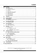
Contents About This Manual ...................................................................................................................................1 1.0 Introduction ..................................................................................................................................1 1.1 1.2 1.3 1.4 1.5 1.6 1.7 1.8 1.9 1.10 2.0 3.0 4.0 Operating Modes . . . . . . . . . . . . . . . . . . . . . . . . . . . . . . . . . . . . . . . . . . . . . . . . . . . . . . . . . . . . . .
About This Manual This manual is intended for use by service technicians responsible for installing and servicing the IB Series electronic tuning fork scale. Configuration and calibration of the scale can be accomplished using the IB Series front panel keys. 1.0 Introduction The IB Series is an advanced precision weighing instrument utilizing a high-precision electronic tuning fork sensor which provides stable measurement over years of usage.
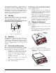
Immediately after unpacking, a visual inspection of the instrument should be conducted. Keep the scale in an upright position. The shipper and Rice Lake Weighing Systems should be notified immediately if a ny d a m a g e o c c u r r e d d u r i n g t r a n s p o r t a t i o n . Instructions for assessment of damage and further procedures will then be determined. 1.3 Unlocking Locate a black rubber cap at the top of the scale. Remove the cap to find a lock lever in it.
1.7 Leveling the Scale The scale must be level for proper operation. Use the four level adjusters located at the four corners of the scales main unit to adjust the horizontal position of the scale until the bubble of the level indicator lies within the red circle. Ensure that the scale sits solidly and does not wobble due to uneven adjustment. LEVEL INDICATOR BLUE CIRCLE ADJUSTERS BUBBLE Figure 1-4. Bubble Adjustment 1.
1.9 Front Panel Keypad Table 1-1 on page 4 shows the IB Series LED annunciators, keypad, and normal mode key functions. RICE SLEEP LOW-BATT P LAKE IB T F Figure 1-6. Front Panel Keypad The LCD annunciators shown on the IB Series front panel describe the indicator functions assigned in setup mode. In setup and calibration mode, the keys are used to navigate through menus, select digits within numeric values, and increment/decrement values.
The front panel operation key symbols describe the functions assigned to the scale. Function Operation Key Sets limit function or cancels functions P • Sets and memorizes data in the count mode and when the limit function is operating. • Calls up and selects functions and items. • Selects row during numerical setting (limit function). F • Selects operation zero and tare subtraction. • Selects input numeral during numerical setting (limit function). T Table 1-2. Front Panel Key Functions 1.
2.0 Calibration This section describes procedures for calibrating the IB Series scale. Follow the steps in Table 2-1 to calibrate the IB Series scale. Action Step 1 Hold down the F key until [Func] ➙ [CAL] appear in sequence, then release the key. 2 Hold down the T key, then press the F key, then release both keys. 3 The display will show [unit]. Select weight unit from parameters “1” to “d”, by pressing the T key. The contents of the parameters are the same as at function [71 uA].
3.0 Measuring Weight This section describes procedures for tare subtraction and weighing on the IB Series scale. Follow the steps below for tare subtracting and weighing on the IB Series scale. 1. Place a container on the weigh pan, press the T key. The zero display appears. Tare Subtraction 0.0 P F g T 2. Place the product in the container. The net weight is displayed. Net Weighing 1234.5 P 3. If you wish to remove the product or to return the display to zero, press the T key.
4.0 Count Weighing Count weighing is used to determine piece count rather than weight. In order for the scale to perform this function it must know the average piece weight. By loading a specified number of pieces on the pan and entering that count, the scale calculates and stores in memory the piece weight for that product. This process is referred to as “sampling.” For example, ten pieces are placed on the scale. When “10” is entered, the unit piece weight is set.
3. If the weighing mode display appears, press the T key to enter the count mode. 1.SET 1 ➩ P 4. To exit the function setting display and enter the count mode press the P key. Count Mode Weighing Mode F 1.SET 2 P T T Exit Mode Settings 0 P 4.2 F pcs. F T Self Counting System Self Counting System (SCS) allows the user to start with any sample quantity selected. The concept of SCS keeps the user within built-in parameters.
4. Place the selected number of items in the tare vessel a n d t h e n p r e s s t h e F key. T h e d i s p l a y w i l l temporarily go blank and a tone will be emitted, indicating the quantity has been memorized. The ["] flashes, indicating that memory is being updated. 5. If additional items are placed in the tare vessel (maximum of three times the displayed quantity), the new quantity will be memorized. A tone will then be emitted indicating the new quantity has been memorized.
5.0 Calculation Factor Mode In calculation factor mode, the desired index is memorized, the index for the weight of the item placed on the scale is calculated and the calculated value is displayed. This allows conversion into various units. 5.1 Method of Operation 1. Hold down the F key until [C Set] appears. The [M] symbol and the display begins flashing. If a reference value has already been set, that value displays. C. SET P 2.
6. When an item is placed on the scale, the index of its weight is calculated and the calculated value displays. This display is equal to the index (1.23) times the weight of the item (100 g). Measurement of Index 123.
6.0 Percentage Mode The weight of the sample selected as the reference is memorized as 100%. The ratio between the item being measured and the reference is displayed as a percentage. 6.1 Setting Actual Weight 1. Press the T key to zero the scale. This operation is also performed if the tare vessel is used. Zero Scale 0% P 2. Continuously press the F key until [P SEt] displays. The [M] symbol and the display flash. If a reference value has been previously set, that value displays. ➩ ➩ P.
6.2 Setting Numerical Value 1. Press the F key until the [P SEt] message is displayed. The [M] symbol and the setting value flashes on the display. If the reference value has been previously set, that value is dislayed. P. SET P 2. Press the T key until the [0] displays to the right side and the bar graph underneath flashes. The desired value can now be set. ➩ ➩ F Setting Index Value 0.00 % T Start Numeric Input 0.0 % P 3.
7.0 Functions The following sections describe the functionality of the IB Series scale. 7.1 Selecting Functions 1. Hold down the F key for about four seconds. Release when the [Func] display appears. Function Access FUNC P 2. The first item of the function display appears: mode type. F T Mode Type 1.SET 1 P F T Each time the F key is pressed, the function item displays appear in sequence. Mode Type ➩ 1.SET 1 P F Comparator Contents Simple Weighing Function 2.SEL 1 ➩ P T F 21.CO.
3. To alter the setting, press the T key with the desired function display showing. (See Table 7-1 on page 17). ➩ 5. RE. 1 ➩ P 4. After confirming the change, press the P key. The function setting is complete and the display returns to the operational mode. IB Series Operation Manual T P ➩ 5. RE. 1 ➩ P 16 F 5. RE. 5 F T F T 0.
7.2 Function List Display 1.SEt * 2.SEL * Function 1 * * 3 Percentage Mode + weighing 4 Weight conversion + weighing 1 Simple Weighing Function Only when setting value Accumulation Function On 3 Comparator Function On 4 Accumulation Function + Comparator Function Auto Zero [34] is selected. Proceed to type 21 function. No adjustment of zero point 1 Automatic adjustment of zero point Auto Power Off With Battery Option 1 1 * Additional Functions 2 0 5.
Display 71 uA Function 1 2 72 dA Weighing Unit Description Group “A” mg g 3 kg 4 ct 5 oz 6 lb 7 ozt 8 dwt 9 gr A tl (Hong Kong) B tl (Singapore, Malaysia) C tl (Taiwan) D mon 1 2 Least Readability Fine Ex. IB-2000 3 4 Coarse 5 Table 7-1. Function List (Continued) 18 IB Series Operation Manual 0.001g 0.02g 0.05g 0.1g 0.
Display 73 uA Function 0 1 74 dA Weighing Unit Description Group “B” No unit displayed mg 2 g 3 kg 4 ct 5 oz 6 lb 7 ozt 8 dwt 9 gr A tl (Hong Kong) B tl (Singapore, Malaysia) C tl (Taiwan) D mon 1 2 Least Readability Fine Ex. IB-2000 3 0.001g 0.02g 0.05g 0.1g 0.2g 4 Coarse 5 Table 7-1. Function List (Continued) * = indicates default setting at time of factory shipment. Notes: • If activate comparator function is selected, the comparator function data shown in Figure 7.
7.2.1 Comparator Function Data Display 21.Co * Contents 1 Judgment Condition 2 22.Li * 0 24.Bu * 25.LG * 1 Judgment even when scale unstable Judgment only when scale is stable Judgment Range 1 23.Pn Description No judgment around zero point Total range includes zero point Number of Setting Points Setting point no. 1 2 Setting point no. 2 3 Setting point no. 3 4 Setting point no.
7.2.2 Interface Data Display 81 oc * 82 bL. * Item 0 Status Output Control Output disabled 1 Normal operation, continuous output 2 Continued output when stable (stop if unstable) 3 Press the P key X 1 to ouput (manual) printer X 1 4 Automatic output X 1 after load stabilized 5 Stable = output X 1; unstable = no output 6 Stable = output X 1; unstable = continue output 7 Press the P key once to output X 1 1 Baud Rate 1200 BPS 2 2400 BPS 3 4800 BPS Table 7-3.
8.0 Comparator Function The comparator function is convenient for classifying weighing items according to pre-determined weight ranges. The upper and lower limits of this range are stored in the scale’s memory, and when an item is placed on the weighing pan it is judged as either acceptable or unacceptable. This function can only be used in weighing mode. 8.1 Upper and Lower Limit Setting Procedure To set the upper and lower limits, follow this procedure while referring to Section 8.3 on page 24. 1.
6. Press the F key. The first limit function display appears. Press the F key repeatedly to call up the limit function displays in sequence. Limit Function Data 21.CO.2 LIMIT FUNCTION DISPLAYS: F T ➩ P Range Buzzer ON 23.BU.0 ➩ P 7. To change the setting parameters, press the T key with the desired limit function display showing. P T ➩ 21,CO. 1 ➩ All Status Judgement P 8. After each parameter is set, press the P key to return to weighing mode. F F ➩ 21,CO. 2 ➩ F T 21.CO.
2. Press the P key to display H.SEt (high [upper] limit set). The [ " ] indicator next to OVER flashes and the lower limit value is displayed. Setting Start H. SET P F Upper Limit Value ➩ 567.8 P T 3. Press the P key to end setting sequence and return to weighing mode. F g T End Setting 0.0 P F g. T Note: If the L.SEt display does not appear, the scale is not in function setting mode, or the count mode is in effect (pcs displayed as unit indicator). 8.
2. Place a sample of the actual lower limit weight on the weigh pan and press the F key. The display goes blank for a moment while the lower limit value is memorized. Memorize Upper Limit Place Low Sample 123.4 P 3. Press the P key to change to the upper limit setting display. The indicator next to OVER flashes. Upper Limit Setting H. SET P 4. Place a sample of the actual upper limit weight on the weigh pan and press the F key.
2. Press the T key to commence value setting. All digits are displayed and only the lowest digit flashes to indicate that input can be made to that position. Start Numeric Input 0000.0 P 3. Press the T key again to select a numeral. Each time the key is pressed, a new numeral is advanced. F 1 2 ....... 3 0000.4 Move Input Digit 0000.4 P 5. Continue entering the required numerals as above. When all numerals have been entered, press the P key to record lower limit value in memory.
9.0 Accumulation Function The accumulation function of the IB Series offers summing-up and display of measured data repeatedly. Useful in mixing or filling applications. 9.1 Operation 1. Load an object on the scale. When the display shows , press the P key to accumulate the display value. The total value and ∑ is displayed for a moment. Accumulation 100 P 2. Unload the object and allow the balance to stabilize and re-zero. Display will show .
10.0 Specifications This section contains charts for specifications and model data for the IB Series scale. 10.1 Specifications Refer to the tables below for common specifications and model specific data. 10.1.
10.2 Options and Standard Attachments Options • • • • • IJ output: for connecting peripherals (printer, comparator, etc.) Buzzer output: judgment result alert buzzer function + IJ output. Limit output: judgment result alert buzzer connection output + specialized printer output. RS-232C output: for two-way communication with peripheral or external units. Battery drive: 48-hour charge (when not using output) for use where no service outlet is available. Standard Attachments • • AC Adaptor Dust cover 10.
IB-5000 Set C IB-10K Unit Mark Capacity Readability 1 mg mg 5,000,000 100 2 g g 5,000 3 kg kg 4 ct 5 Set C Unit Mark Capacity Readability 1 mg mg 10,000,000 50 .01 2 g g 10,000 .05 5 .0001 3 kg kg 10 0.00005 ct 25,000 .5 4 ct ct 50,000 0.2 oz # 170 0.002 5 oz # 350 0.002 6 lb # 11 0.0002 6 lb # 22 0.0001 7 ozt # 160 0.002 7 ozt # 320 0.002 8 dwt # 3,200 0.05 8 dwt # 6,400 0.05 9 gr # 77,000 2 9 gr # 150.
11.0 Troubleshooting The following section contains a troubleshooting chart for the IB Series scale. Refer to this chart to locate causes and countermeasures to various conditions. Condition Limit function data cannot be set Cause • Scale is not set to Limit Function mode • Upper and lower limits have not been set, or lower limit upper limit setting has been entered Countermeasure • Check that limit function settings are correct: See page 27 [#] mark will flash at OVER/ACCEPT/ UNDER positions.
IB Series Limited Warranty Rice Lake Weighing Systems (RLWS) warrants that all RLWS equipment and systems manufactured and sold by RLWS and properly installed by an authorized RLWS Distributor or Original Equipment Manufacturer (OEM) will operate per written specifications as confirmed by the Distributor/OEM and accepted by rlws. All systems and components are warranted against defects in materials and workmanship for five years.