RL1600 Weigh Module Kit Installation Guide 16952 11
Contents 1. Introduction ............................................................................ 1 2. Mechanical Installation .......................................................... 2 2.1 General Installation Guidelines for Weigh Modules .................... 2 2.2 Installing the RL1600 .................................................................. 3 3. Load Cell Wiring ..................................................................... 5 4. Junction Box Connections, Adjustments & Calibration.
1. Introduction The RL1600 Weigh Module Kit provides an extremely accurate method for weighing medium and large capacity tanks, hoppers, bins, and reactors. The design uses a double-ended shear beam load cell (700Ω bridge) and transmits the load through a clamping load plate to the center of the load cell. This design is very effective in providing for thermal expansion/contraction with little friction.
2. Mechanical Installation 2.1 General Installation Guidelines for Weigh Modules 1. The mounting surface for the base and top plate must be level. After installation, the top and bottom plates must be level within ±0.5°. If the mounting surfaces are not level, then shims and or grout may be used to level the mount.
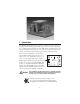
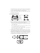
frequently steam cleaned or if the load cell is subjected to direct washdown, a protective shroud for the weigh module is recommended. Proper drainage is necessary so the weighing assembly is not standing in water. 7. All support points should be equally stiff so that they deflect by the same amount as the vessel is loaded. 2.2 Installing the RL1600 Load Plate and Clamp Pin Cotter Pin Flat Washer Load Cell Lockwasher Clamp Bolt Tank Mount Base 1.
3. Assemble the modules by attaching the load cell to the load plate and clamp using the lockwashers and clamp screws. Then, insert the load pins through the base plate and load cell. Secure the load pins with washers and cotter pins. Note: The arrow on the load cell should point in the direction of the load. 4. Lift and block the vessel to the same height as the assembled modules. 5. Remove the block from one support point and slide that module into position. 6.
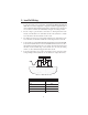
3. Load Cell Wiring 1. Route the load cell cables so they will not be damaged or cut. Cable should not be routed near heat sources greater than 150 °F. Do not shorten any load cell cable. The load cell is temperature compensated with the supplied length of cable. Cutting the cable will affect temperature compensation. Coil and protect excess cable so it will not be mechanically damaged or be sitting in water. 2.
4. Junction Box Connections, Adjustments & Calibration 1. Refer to the Junction Box manual for trimming details. 2. Refer to the indicator manual for system calibration details. 5. Troubleshooting If the system powers up and gives some type of stable digital readout that varies with the load on the system, any system problems are probably caused by factors other than the load cells. The load cells are often blamed for a malfunctioning system, but 90% of the time, the problem lies elsewhere.
7. Check possible indicator malfunction by using a load cell simulator to input a known good signal into the indicator. 8. Disconnect each load cell’s signal leads at the junction box and check individual load cell outputs with a multimeter. Then check input/output impedances for comparison with load cell manufacturer’s specifications. If after all these checks the problem still cannot be isolated, reconnect all but one load cell. Replace the load cell with a load cell simulator.
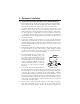
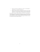
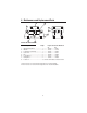
6. Maintenance and Replacement Parts 3 8 4 2 5 1 6 7 RL1600 CAST IRON MODULES No. Description 1 ... 2 ... 3 ... 4 ... 5 ... 6 ... 7 ... 8 ... Reqd. Replacement Part Numbers A* B* Weigh Module Base ................... 1 ............ 18439 ......... 18441 Washer ....................................... 4 ............ 15165 ......... 15179 Load Plate and Clamp ................ 1 ............ 18443 ......... 18445 Cotter Pin .................................... 4 ............ 15232 ......... 15237 Pin ...
3 4 8 2 5 1 6 7 RL1600 MILD STEEL MODULES No. Description 1 ... 2 ... 3 ... 4 ... 5 ... 6 ... 7 ... 8 ... Reqd. Replacement Part Numbers A* B* C* D* Weigh Module Base ................... 1 ....... 22745 .. 22748 ... 22751 .. 22751 Washer ....................................... 4 ....... 15165 .. 15179 ... 15188 .. 15188 Load Plate and Clamp ................ 1 ....... 22746 .. 22749 ... 22752 .. 25364 Cotter Pin .................................... 4 ....... 15232 .. 15237 ... 15257 .. 15257 Pin ......
7. RL1600 Limited Warranty Rice Lake Weighing Systems (RLWS) warrants that all RLWS equipment and systems properly installed by a Distributor or Original Equipment Manufacturer (OEM) will operate per written specifications as confirmed by the Distributor/OEM and accepted by RLWS. All weigh modules are warranted against defects in materials and workmanship for two (2) years. RLWS warrants that the equipment sold hereunder will conform to the current written specifications authorized by RLWS.