
Owner manual


6
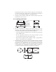
4. Junction Box Connections, Adjustments & Calibration
1. Refer to the Junction Box manual for trimming details.
2. Refer to the indicator manual for system calibration details.
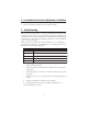
5. Troubleshooting
If the system powers up and gives some type of stable digital readout that varies
with the load on the system, any system problems are probably caused by factors
other than the load cells. The load cells are often blamed for a malfunctioning
system, but 90% of the time, the problem lies elsewhere. Look for mechanical
causes for your problem first.
If the system can be calibrated but doesn’t return to zero, loses calibration, or
demonstrates non-linearity or non-repeatability, see the following chart for pos-
sible causes and do the following checks.
1. Check weigh module for debris restricting load cell movement or debris
between scale and structure.
2. Check that tank/vessel and modules are plumb, level, and square at the
critical areas.
3. Check all piping and conduit for connections which restrict vessel
movement.
4. If check rods are used, loosen all connections to finger tight only for
testing.
5. Check load cell cables for physical or water damage.
6. Check all electrical connections, especially in the junction box.
If the problem still is not found:
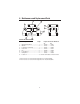
motpmySmotpmyS
motpmyS
motpmySmotpmyS esuaCelbissoPesuaCelbissoP
esuaCelbissoP
esuaCelbissoPesuaCelbissoP
orezotnruteroN noitarbilacmetsystsolevahyam;sllecdaolrednuroslaesnisirbedrognidniblacinahceM
ytiraenil-noN daoledisrognidnibgnisuacdaolrednunoitcelfedronoisnapxelamrehT
ytilibataeper-noN
;egamadkcohsrodaolrevollecdaol,erutsiomybdesuacgnitfird;tnuomllecdaolesooL
gnidniblacinahcem
noitarbilactsoL gnidniblacinahcem;melborperutsiom;bmulprolevelfotuO
tuodaergnitfirD gnidniblacinahcem;llecdaolro,selbac,xobnoitcnujnierutsioM