
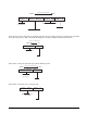
Troubleshooting guide


26 Summit SB-1000 Bariatric Wheelchair Scale Installation Manual
Figure 8-4. Foot Pad - Side View
Route the load cell cables near each corner so that the
cable is free from possible contact with each foot.
Hold the cable in position with the supplied
adhesive-backed cable ties.
Do not cut load cell cables. Coil extra cable before it
enters the junction box, tie with cable ties, and insert
the coils into the channel near the junction box.
After coiling excess cable, pass each individual end of
load cell cable through its grommet in the junction
box cover (or through cable fittings in the NEMA 4X
junction box).
Corner correction trimming and calibration is
necessary after load cell replacement. Follow
instruction in Sections 3.2 on page 5.
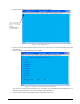
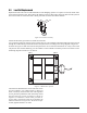
8.3.1 Load Cell Wiring to Junction Box
The four load cells are each wired to their respective
terminals in the junction box according to the corner
numbering system shown in
Figure 8-5, and the
coloring code in Table 8-3.
Pull excess cable out of the junction box enclosure
and tighten the cable grips with a wrench. To be
watertight, the cable grips must be tightened to the
point where the rubber sleeving begins to protrude out
of the hub. Finally, pull on each of the four cables to
make sure that they do not slip.
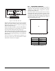
Figure 8-5. Corner Numbering - Top View
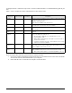
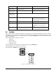
,o,NPEFMT
Cable Color Code J-Box Terminal
Red +Excitation
Black -Excitation
Green +Signal
White -Signal
Table 8-3. Load Cell Wiring
1
4
2
3