利佳興業股份有限公司 RICH ELECTRIC CO.,LTD.
CONTENTS Specifications ..................................................................................................................................I Chapter 1 SunStar Description................................................................................................. 1-1 1.1 Versions and Ratings ....................................................................................... 1-1 1.2 Operating Modes.........................................................................................
4.5 Float................................................................................................................... 4-6 Chapter 5 Load Control ............................................................................................................ 5-1 5.1 Load Control Settings...................................................................................... 5-1 5.2 Inductive Loads (Motors)................................................................................ 5-1 5.
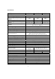
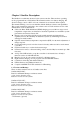
Specifications MODEL ELECTRICAL System voltage ratings Current ratings-Battery Charge Control Current ratings-Load Control Current ratings-Diversion Charge Control Accuracy Min. voltage to operate Max. solar array Voc Max. operating voltage Total current consumption High temp shutdown SS-30C SS-60C 12, 24, 48 Vdc 30A 45A 60A 30A 45A 60A 30A 45A 60A Diversion load Diversion load Diversion load 12/24V:≦0.1 % ± 50 mV 48V:≦0.
Chapter 1 SunStar Description The SunStar is a technically advanced solar system controller. There are three operating modes programmed into each SunStar. The manual describes solar battery charging, DC diversion charge control or DC Load control instructions are inserted where required. The manual will help you to become familiar with the SunStar’s features and capabilities. This operation manual is applicable to the software version V1.05 and later version of the SunStar units.
1.2 Operating Modes There are three distinct and independent operating modes programmed into each SunStar. Only one mode of operation can be selected for an individual SunStar. If a system requires a charging controller and a load controller, two SunStars must be used. Solar Battery Charging The energy output of a solar array is used for recharging the system battery. The SunStar manages the charging process to be efficient and to maximize the life of the battery.
DIP switch 4~6 7 (OFF) (ON) 8 (OFF) (ON) Load control Standard low voltage disconnects and reconnects Manual reconnect for Dip Switch 4~6 standard low voltage Auto reconnect for Dip Switch 4~6 standard low voltage Operating from Dip Switch 4~6 standard low voltage disconnects and reconnects VR1 and VR2 settings for user define low voltage disconnects and reconnects 1.4 General Use NOTE: This manual describes solar battery charging.
1.5 Optional Available Three optional components can be added to the standard SunStar controller at any time. ※ Battery Temperature Sensor (BTS) If the temperature of the system battery varies more than 5°C during the year, temperature compensated charging should be considered. Because the battery’s chemical reactions change with temperature, it can be important to adjust charging to account for the temperature effects.
Chapter 2 SunStar Installation The installation instructions describe solar battery charging. Specific instructions for the load control and diversion modes are provided as notes. 2.1 General Information The mounting location is important to the performance and operating life of the controller. The environment must be dry and protected as noted below. The controller may be installed in a ventilated enclosure with sealed batteries, but never in a sealed battery enclosure or with vented batteries.
2.
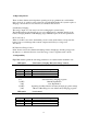
PV+/ BAT+ LOA D+ GND G ND D C Load or Solar Array Ground BATTERY BTS Installation wiring for solar charging or DC load control Solar charging or DC load control: Step 1: Open the access cover Step 2: Mount the SunStar using the enclosed template. Step 3: Adjust the 8 switches in the DIP switch. Each switch must be in the correct position. Step 4: Attach the BTS if battery charging will be temperature compensated (not for load control). Step 5: Connect the battery power wires to the SunStar.
DC diversion charge control: Step 1: Open the access cover Step 2: Mount the SunStar using the enclosed template. Step 3: Adjust the 8 switches in the DIP switch. Each switch must be in the correct position. Step 4: Attach the BTS if battery charging will be temperature compensated Step 5: Connect the battery power wires to the SunStar. Then connect the diversion load wires. Step 6: Close the cover. ※ Step 4 is optional. 2.
2.4.1 Mounting Unit: mm Mounting Dimensions z Locate the SunStar on a wall protected from direct sun, high temperatures, and water. Do not install in a confined area where battery gasses can accumulate. z When mounting the SunStar, make sure the air flow around the controller and heat sink is not obstructed. There should be open space above and below the heat sink, and at least 75 mm (3 inches) clearance around the heat sink to allow free air flow for cooling.
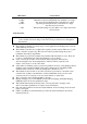
ON ON O FF D IP 1 2 3 4 5 6 7 8 C o n tro l M o d e (1 ) B a tte ry C h a rg in g (d iv e rs io n c h a rg e c o n tro l) S y s te m V o lta g e (2 ,3 ) B a tte ry C h a rg in g a lg o rith m (4 ,5 ,6 ) M a n u a l/A u to E q u a liz a tio n (7 ) U se r D e fin e C h a rg in g a lg o rith m (8 ) DIP Switch Functions ※ As shown in the diagram, all the positions are in the “OFF” position except switch number 3 and 7 which are in the “ON” position.
DIP Switch Number 2, 3-System voltage Switch 2 Switch 3 System Voltage OFF OFF 48V system ON OFF 24V system OFF ON 12V system DIP Switch Number 4, 5, 6-Battery charging algorithm DIPSW-4 DIP SW-5 DIP SW-6 Bulk voltage Float voltage Equalize Voltage OFF OFF OFF OFF ON ON ON ON OFF OFF ON ON OFF OFF ON ON OFF ON OFF ON OFF ON OFF ON 14.0V 14.1V 14.3V 14.4V 14.6V 14.8V 15.0V 16.0V 13.4V 13.4V 13.4V 13.4V 13.4V 13.4V 13.4V 14.5V None 14.2V 14.4V 15.1V 15.3V 15.3V 15.
for the timer to start counting-the voltage may not reach the equalization voltage setting. To manually stop the equalization process, press the reset pushbutton and the status LED will stop, if the equalization process was shorter than one hour, the controller will continue with a bulk charge cycle and then hold the battery at the bulk setting for one hour (the absorption voltage) before returning to the float setting.
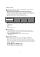
ON ON OFF D IP 1 2 3 4 5 6 7 8 C o n tro l M o d e (1 ) D C L o ad C o n tro l S y stem V o ltag e (2 ,3 ) L V D / L V R (4 ,5 ,6 ) A u to / M an u al L V R (7 ) U ser D efin e L V D /L V R (8 ) Load Control DIP Switch Functions ※ As shown in the diagram, all the positions are in the “OFF” position except switch number 1, which is in the “ON” position. NOTE: The DIP switches should be changed only when there is no power to the controller.
DIP Switch Number 4, 5, 6-Load Control Algorithm LVR DIPSW-4 DIP SW-5 DIP SW-6 12V 24V OFF OFF OFF 12.6V 25.2V OFF OFF ON 12.8V 25.6V OFF ON OFF 13.0V 26.0V OFF ON ON 13.2V 26.4V ON OFF OFF 13.4V 26.8V ON OFF ON 13.6V 27.2V ON ON OFF 13.8V 27.6V ON ON ON 12.0V 24.0V Select 1 of the 8 standard load control algorithms. 48V 50.4V 51.2V 52.0V 52.8V 53.6V 54.4V 55.8V 48.0V 12V 11.1V 11.3V 11.5V 11.7V 11.9V 12.1V 12.3V 10.5V LVD 24V 22.2V 22.6V 23.0V 23.4V 23.8V 24.2V 24.6V 21.0V 48V 44.4V 45.2V 46.0V 46.
2.4.4 Diversion Charge Control DIP Switch Setting Diversion charge control DIP switch settings are exactly the same as solar battery charging DIP switch setting which can be referred to 2.4.2 description. 2.4.5 Battery Temperature Sensor (BTS) For solar battery charging and diversion load control, a Battery Temperature Sensor (BTS) is recommended for effective temperature compensated charging. This Battery Temperature Sensor should not be installed for DC load control.
Notes: z The specified wire length is for a pair of conductors from the solar, load or battery source to the controller (1-way distance). z Figures are in meters (m) and feet (ft). z For 24 volt systems, multiply the 1-way length in the table by 2. z For 48 volt systems, multiply the 1-way length in the table by 4. Ground Connection: Use the grounding terminal in the wiring compartment to connect a copper wire to an earth ground or similar grounding point.
CAUTION: The solar PV array can produce open-circuit voltages over 100 Vdc when in sunlight. Verify that the solar input breaker has been opened (disconnected) before installing the system wires (if the controller is in the solar charging mode). Using the diagram on the previous pages, connect the four power conductors in the following steps: 1. Confirm that the input and output disconnect switches are both turned off before connecting the power wires to the controller.
2.5 Communication with CombiPlus/SuperCombi SunStar Series can not only operate alone when the BCD Switch is placed at 0 but also communicate with CombiPlus/SuperCombi up to 10 units together when BCD Switch is placed at 1~A. The example of how to wire 1 unit of the SunStar and how to wire 2~10 units to CombiPlus/SuperCombi is demonstrated in the following.
The Wiring of 2~10 units of SunStar to Communicate with CombiPlus/ SuperCombi COMBI PLUS / SUPERCOMBI POS+ PORT A (IN) PORT B (OUT) PORT C (EXT) AC INPUT BREAKER 1 V-SENS BTS CHARGE RY1 A B RY2 C A B RY3 C A C NEG- SUN STAR SOLAR PANEL BAT+ PV+A GND AC OUT AC IN L N G G N L GND IN OUT RJ-45 Cable 2 BATTERY SUN STAR SOLAR PANEL BAT+ PV+A GND GND IN OUT RJ-45 Cable 3 SUN STAR SOLAR PANEL BAT+ PV+A GND GND RJ-45 Cable IN OUT 2-15
Chapter 3 Front Cover of SunStar Operation There are 4 LEDs, 1 LCD Meter of 16 x 2 characters and 2 pushbuttons on SunStar front cover.
3.1 LED Status Indicators Four LED indicate operating status of the controller. When the controller is in Charge Control Mode (or Diversion Charge Control Mode), the charge mode (green) LED will blink. When in Load Control Mode, the Load Control Mode (red) LED will blink. When battery equalization is in process, the Equalization (orange) LED is blinking. A red LED solid or blinking indicates a fault condition. 3.
“Load Control Mode LED” Blinking Red: As battery voltage approaches the LVD setting, the LED will blink red several times (up to five) and then pause providing an indication of battery voltage. Refer to Table 2 to determine the battery voltage. LED Status Always ON 5 Blinks 4 Blinks 3 Blinks 2 Blinks 1 Blinks DC Voltage Battery Voltage (Using LED Status Indicator) Red LED (Load Control Mode) Battery at LVD setting (for 6 minute=LVD) >0.15 >0.3 >0.45 Above LVD Above LVD Above LVD LVD Setting Plus (+) 0.
Blinking Red: In DC Load Control Mode, the controller is in the status of battery low voltage disconnect. Details of the fault messages could be referred to 3.6.2 Fault Messages. 3.6 LCD Meter Displays Two optional LCD digital meter displays are available for SunStar controllers: The SS-D LCD Meter Displays is standard faceplate on the SunStar Controller and the other SS-RD can be mounted remotely. The remote version is available with either 50 feet or 100 feet cables.
3-5
3-6
Chapter 4 Solar Battery Charging 4.1 PWM Battery Charging PWM (Pulse Width Modulation) battery charging is the most efficient and effective method for recharging a battery in a solar system. Selecting the best method for charging your battery together with a good maintenance program will ensure a healthy battery and long service life.
Some useful functions to know follow below. Solar Overload: Enhanced radiation or “edge of cloud effect” conditions can generate more current than the controller’s rating. The SunStar will reduce this overload up to 130% of rated current by regulating the current to safe levels. If the current from the solar array exceeds 150%, the controller will interrupt charging. Battery Temperature Compensation: All charging setpoints are based on 25°C (77°F).
A. Battery Type– These are generic lead-acid and Ni-cad battery types. See Section 8.0 for more information about battery types and appropriate solar charging. B. BULK Voltage–This is the PWM Absorption stage with constant voltage charging. The “PWM voltage” is the maximum battery voltage that will be held constant. As the battery becomes more charged, the charging current tapers down until the battery is fully charged. C.
Float Float is less affected by temperature changes, but it may also undercharge or gas too much depending on how much the temperature changes. The BTS corrects the three charging setpoints noted above by the following values: • 12 volt battery: –0.030 volts per °C (–0.017 volts per °F) • 24 volt battery: –0.060 volts per °C (–0.033 volts per °F) • 48 volt battery: –0.120 volts per °C (–0.067 volts per °F) Variations in battery temperature can affect charging, battery capacity, and battery life.
battery is fully recharged. However, a solar battery is seldom completely recharged, so the soft lead sulfate crystals harden over a period of time. Only a long controlled overcharge, or equalization, at a higher voltage can reverse the hardening sulfate crystals. In addition to slowing or preventing lead sulfation, there are also other benefits from equalizations of the solar system battery. These include: Balance the individual cell voltages.
mode. 4.4.2 Typical Equalizations The automatic equalizations will occur at the selected charging program from Dip Switch 4~6. When an equalization begins (auto or manual), the battery charging voltage increases up to the equalization voltage (Veq). The battery will remain at Veq for the time specified in the selected charging program. The equalization process will continue until the voltage has been held above the bulk setting for a cumulate period of two hours.
Chapter 5 Load Control This section describes the user selectable load control settings (5.1) and the low voltage load disconnect (LVD) warning indications (5.2). Load information and general cautions are provided in the remaining sections. 5.1 Load Control Settings The primary purpose of a low voltage load disconnect function (LVD) is to protect the system battery from deep discharges that could damage the battery.
PV+/LOAD+ DC Motor SUNSTAR Figure 5.3 Diode Protection The specifications for the diode follow: • a power diode • rated equal or greater than 80 volts • rated equal or greater than 45 amps (SS-45C) or 60 amps (SS-60C) For large inductive loads, a heat sink for the diode may be necessary. 5.3 General Load Control Notes In addition to the inductive loads discussed above, there are a few other load issues that require attention: 5.3.1 Inverters Inverters should never be connected to the SunStar. 5.3.
damaged. CAUTION: Carefully verify the polarity (+ and –) of the load connections before applying power to the controller.
Chapter 6 Diversion Charge Control The SunStar’s third mode of operation is diversion load battery charge control. As the battery becomes fully charged, the SunStar will divert excess current from the battery to a dedicated diversion load. This diversion load must be large enough to absorb all the excess energy, but not too large to cause a controller overload condition. 6.
All values are 25ºC (77ºF). A B C DIP Switches Bulk Float Equalize (4-5-6) Voltage Voltage Voltage off-off-off 14.0 13.4 None off-off-on 14.1 13.4 14.2 off-on-off 14.3 13.4 14.4 off-on-on 14.4 13.4 15.1 on-off-off 14.6 13.4 15.3 on-off-on 14.8 13.4 15.3 on-on-off 15.0 13.4 15.3 on-on-on 16.0 14.5 VR2 VR1 VR2+1V 8-on Table 6.3 Standard Diversion Charging Programs D Equalize Time (hours) 1 2 3 3 3 3 2 E Equalize Interval (days) 28 28 28 28 28 14 7 A.
elements are reliable and widely available. Heating elements are also easy to replace, and the ratings are stable. NOTE: Do not use light bulbs, motors, or other electrical devices for diversion loads. These loads will fail or cause the SunStar to disconnect the load. Only heating elements should be used. Water heating elements are typically 120 volts. Elements rated for 12, 24 and 48 volts are also available, but more difficult to source. The derating for 120 volt heating elements is discussed in 6.4.
6.4.4 Maximum Diversion Load The diversion load should never exceed the SunStar’s current rating (30A or 45A or 60A). Note that the load is not limited by the source (wind, hydro), and will draw its rated current from the battery. The following table specifies the absolute maximum diversion loads that can be used with each SunStar version. These loads (heating elements) are rated for the same voltage as the system voltage.
SS-45C will not provide the 150% diversion load margin, and the SS-45C is only rated for 30A of source current. The SS-45C will not provide enough margin for wind gusts and overloads, so a SS-60C should be used. The diversion load should be sized for 52.5A (150% of the source current) up to 60A (the rating of the SS-60C). If 55A is selected for the diversion load, the load must be capable of diverting 55A at 30V (maximum battery voltage).
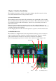
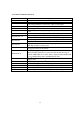
Chapter 7 Trouble Shooting The SunStar performs a continuous self-test to monitor controller and system operation. Detected problems are classified as either faults or alarms. Typically, faults are problems that stop the normal operation of the controller and require immediate attention. Alarms indicate an abnormal condition, but will not stop the controller’s operation.
Troubleshooting Load Control No power to the load z DIP switch settings may be wrong (check each switch position carefully) z Controller is in LVD (check the LEDs) z Load circuit breaker or disconnect may be open z Check the load cables for continuity and good connection z An over-temperature condition may have caused the load to be disconnected Troubleshooting Diversion Control z Diversion load is too small so PWM reaches 99% z Diversion load is burned out so PWM reaches 99% z Diversion load is too large s
Chapter 8 Battery Information The standard battery charging programs in the SunStar controller, as described in Section 4.2, are typical charging algorithms for four battery types: • sealed (VRLA) • flooded (vented) • L-16 group • Nicad and NiFe Other battery chemistries of special voltages such as 36V, can be charged using a custom charging algorithm modified with the potentiometers VR2 and VR1. Only the standard SunStar battery charging programs will be discussed here.
may be needed to balance the individual cell voltages. Other Sealed Batteries: Automotive and “maintenance-free” batteries are also sealed. However, these are not discussed here because they have very poor lifetimes in solar cycling applications. NOTE: Consult the battery manufacturer for the recommended solar charging settings for the battery being used. 8.2 Flooded Batteries Flooded (vented) batteries are preferred for larger cycling solar systems.
low antimony and selenium plates can offer fairly good cycling performance, long life, and reduced watering needs. NOTE: Consult the battery manufacturer for the recommended solar charging settings for the battery being used. 8.3 L-16 Cells One particular type of flooded battery, the L-16 group, is often used in larger solar systems. The L-16 offers good deep-cycle performance, long life, and low cost. The L-16 battery has some special charging requirements in a solar system.
Appendix B