Use & Care Manual With Installation Instructions for the Installer Electric Residential Water Heaters With Electronic Control The purpose of this manual is twofold: one, to provide the installer with the basic directions and recommendations for the proper installation and adjustment of the water heater; and two, for the owner–operator, to explain the features, operation, safety precautions, maintenance and troubleshooting of the water heater. This manual also includes a parts list.
Safety Information Safety Precautions. . . . . . . 3, 4 FOR YOUR RECORDS Write the model and serial numbers here: # # Installation Instructions Location. . . . . . . . . . . . . . . . . . 5 Water Connections . . . . . . . . . 6 You can find them on a label on the appliance. Staple sales slip or cancelled check here. Proof of the original purchase date is needed to obtain service under the warranty. Electrical Connections. . . . . . 8 READ THIS MANUAL Operating Instructions Safety Controls . . . . . .
IMPORTANT SAFETY INFORMATION. READ ALL INSTRUCTIONS BEFORE USING. DANGER! WATER TEMPERATURE SETTING Safety and energy conservation are factors to be considered when selecting the water temperature setting of water heater’s thermostat. Water temperatures above 125°F can cause severe burns or death from scalding. Be sure to read and follow the warnings outlined on the label pictured below. This label is also located on the water heater near the thermostat access panel.
IMPORTANT SAFETY INFORMATION. READ ALL INSTRUCTIONS BEFORE USING. WARNING! For your safety, the information in this manual must be followed to minimize the risk of fire or explosion, electric shock, or to prevent property damage, personal injury, or loss of life. Be sure to read and understand the entire Use and Care Manual before attempting to install or operate this water heater. It may save you time and cost. Pay particular attention to the Safety Instructions.
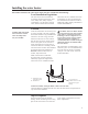
Installing the water heater. The location chosen for the water heater must take into consideration the following: Local Installation Regulations This water heater must be installed in accordance with these instructions, local codes, utility codes, utility company requirements or, in the absence of local codes, the latest edition of the National Electrical Code.
Installing the water heater Thermal Expansion Determine if a check valve exists in the inlet water line. Check with your local water utility. It may have been installed in the cold water line as a separate back flow preventer, or it may be part of a pressure reducing valve, water meter or water softener. A check valve located in the cold water inlet line can cause what is referred to as a “closed water system”.
A new combination temperature and pressure relief valve, complying with the Standard for Relief Valves for Hot Water Supply Systems, ANSI Z21.22/CSA 4.4, is supplied and must be installed in the opening provided and marked for the purpose on the water heater. No valve of any type should be installed between the relief valve and the tank. Local codes shall govern the installation of relief valves.
Installing the water heater Ground screw NING WAR Conduit connector Junction box cover Wire connections Water heater junction box. ! CAUTION: The presence of water in the piping and water heater does not provide sufficient conduction for a ground. Non-metallic piping, dielectric unions, flexible connectors etc. can cause the water heater to be electrically isolated.
Insulation Blankets ! WARNING: If local codes require external application of insulation blanket kits the manufacturer’s instructions included with the kit must be carefully followed. Insulation blankets, available to the general public, for external use on electric water heaters are not necessary. The purpose of an insulation blanket is to reduce the standby heat loss encountered with storage tank heaters.
Installing the water heater Relief Valve Insulation Installation ! CAUTION: Ensure the T&P Valve opening is not obstructed by the insulation. For increased energy efficiency, some water heaters have been supplied with a 2-3/8” section of pipe insulation. Please install the insulation, according to the illustrations above, that best meets your requirements. Slip the insulation cover over the T&P Valve through the center hole and align the hole in the side with the opening of the T&P Valve.
Installation Checklist A. Water Heater Location ❑ Close to area of heated water demand. ❑ Indoors and protected from freezing temperatures. ❑ Area free of flammable vapors. ❑ Provisions made to protect area from water damage. ❑ Sufficient room to service heater. B. Water Supply ❑ Water heater completely filled with water. ❑ Air purged from water heater and piping. ❑ Water connections tight and free of leaks. C.
Operating the water heater CAUTION: Hydrogen gas can be produced in a hot water system served by this water heater that has not been used for a long period of time (generally two weeks or more). HYDROGEN GAS IS EXTREMELY FLAMMABLE!! To dissipate such gas and to reduce risk of injury, it is recommended that the hot water faucet be opened for several minutes at the kitchen sink before using any electrical appliance connected to the hot water system.
Water Temperature Water Temperature Set Point ! DANGER: There is a hot water scald potential if the thermostat is set too high. Households with small children, disabled, or elderly persons may require a 120°F or lower thermostat setting to prevent contact with HOT water. Safety and energy conservation are factors to be considered when selecting the water temperature setting of the water heater’s thermostat(s). The lower the temperature setting, the greater the savings in energy and operating costs.
Programming the Electronic Control Setting the Water Temperature SERVICE NEEDED CLEAR ALARM WiFi SETUP CLEAR ALARM SET POINT (°F) VACATION 110 120 130 140 When power is applied, the water heater will be in a Disabled mode. This means that the water heater is not heating the water and only the power LED is illuminated. Press the RIGHT arrow until the desired temperature is shown.
Locking The Keypad SERVICE NEEDED CLEAR ALARM WiFi SETUP CLEAR ALARM SET POINT (°F) VACATION 110 120 130 140 Press and hold both arrow buttons for 3 seconds to LOCK the control. Locking will reduce chance of unintentional changes in water temperature.
Programming the Electronic Control Vacation Setting Off SERVICE NEEDED CLEAR ALARM WiFi SETUP CLEAR ALARM SET POINT (°F) VACATION 110 120 130 140 Press RIGHT arrow until the desired water temperature is shown on the display. SERVICE NEEDED WiFi SETUP SET POINT (°F) 150 VACATION 110 120 130 140 UNLOCK/LOCK 150 UNLOCK/LOCK (3 SEC) (3 SEC) Heating Status SERVICE NEEDED CLEAR ALARM When the water temperature indicator is blinking, this means that a heating element is on.
WARNING: The use of heat to dry the residual moisture from a spill or leak is NOT PERMITTED. NOTE: The nature of a water heater install often result in spilled water which can trigger the leak detection alarm and closing of shutoff valve, disabling the water heater. 24-Hour Leak Detection Override Prior to using the 24 hour override feature, check to determine the source of the leak.
SERVICE NEEDED Setting Up Wi-Fi Wi-Fi Your heater has integrated Wi-Fi capability. By connecting your heater to the internet, you can access the full benefits of the water heater, including remote control, leak detection alerts, and diagnostic alerts on WiFi device. your mobile CLEAR ALARM SETUP Wi-Fi Setup Procedure Blinking Indicator 1. Upon initial power up, the Wi-Fi module is DISABLED. SERVICE NEEDED SETa. P POINT ress the Wi-Fi(°F) SETUP button for 2 CLEAR ALARM seconds.
Error Codes for Electronic Control NOTE: The EcoNet® app will display all Alerts and Alarms in the EcoNet® app with specifics about the cause.
Care and cleaning of the water heater. Draining the Water Heater CAUTION: Shut off power to the water heater before draining water. DANGER: Before manually operating the relief valve, make certain no one will be exposed to the hot water released by the valve. The water drained from the tank may be hot enough to present a scald hazard and should be directed to a suitable drain to prevent injury or damage.
Care and cleaning of the water heater. Extended Shut-Down NOTICE: Refer to the Hydrogen Gas Caution in the Operating Instructions. If the water heater is to remain idle for an extended period of time, the power and water to the appliance should be turned off to conserve energy and prevent a build-up of dangerous hydrogen gas. The water heater and piping should be drained if they might be subjected to freezing temperatures.
Before You Call For Service… Troubleshooting Tips Save time and money! Review the chart on this page first and you may not need to call for service. Problem Possible Causes What To Do Rumbling noise Water conditions in your home caused a build up of scale or mineral deposits on the heating elements. Pressure build up caused by thermal expansion in a closed system. ● Remove and clean the heating elements. Internal heat trap fittings in operation.
Diagnostic Mode For additional unit information, you can connect directly to the water heater via local mode and use the EcoNet® app for more details alarm and alert information. To connect to the water heater via local mode follow these steps. 3. Press the connect button in the app. 1. Press the Wi-Fi step up button until the unit beeps and the Wi-Fi LED blinks blue. 2. From the EcoNet® app click on Diagnostic Mode. 4. Follow the on screen instructions. 5.
Replacement Parts. Instructions For Placing a Parts Order Address parts orders to the distributor or store where the heater was purchased. art description (as noted below) and P number of parts desired. All parts orders should include: ! CAUTION: For your safety DO NOT attempt repair of electrical wiring, thermostat(s), heating elements or other operating controls. Refer repairs to qualified service personnel. The model and serial number of the water heater from the rating plate.
Cavity Insert Instructions The following instructions are intended for qualified service personnel ONLY, and should only be done when necessary. In order to replace the thermostat or heating element, remove the cavity insert crossbar by following the instructions below: Turn off the power to the water heater. emove the jacket access panel or electronic control R and insulation.
Wiring Diagram This water heater is wired as indicated in the schematic below. Use only a 2 wire power feed with ground connection for this water heater.
Notes: 27
IF YOU NEED SERVICE 1. Should you have any questions about your new water heater, or if it requires adjustment, repair, or routine maintenance, it is suggested that you first contact your installer, plumbing contractor or previously agreed upon service agency. In the event the firm has moved, or is unavailable, refer to the telephone directory, commercial listings or local utility for qualified service assistance. 2.