
Instructions / Assembly

23
Installing the Optional User Display
The following instructions apply only to water
heater models factory supplied with the electronic
display option.
IMPORTANT NOTICE: This electronic display
cannot be added to a water heater not supplied
from the factory with an electronic display.
Components supplied with user display models:
a. Optional Water Heater Mounting Bracket –
AP14752
b. 12 feet, 18 AWG Thermostat Wire – AP14820
c. Optional Mounting Tape – AP14819
d. Transformer Enclosure – AP14875
e. Screw, #8 x ½ in. Self Drilling Qty 2
AP5925GS
f. User Display – AP14697
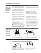
Installation Instructions:
!
CAUTION: Turn the switch on the blower
to the “off” position and disconnect power to
the water heater before proceeding!
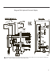
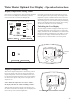
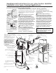
1. Locate the electrical connection for the
Transformer Enclosure on the top of the water
heater. This electrical connection features
a white 6-pin plug and white heat shrink.
(Blower may be different in appearance)
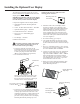
2. The Transformer Enclosure
features a 6-pin connection located on the
circuit board inside the enclosure. Attach
the top pan harness connector to this 6-pin
connector in the correct orientation.
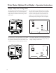
3. Locate the two screw pilot holes on the water
heater top to attach the Transformer Enclosure
to the top pan. Position the enclosure so the
terminal strip opening is visible from the front
of the water heater. Secure enclosure to top
pan with screws provided in the User Display
Mounting Kit without pinching any wires.
NOTICE: DO NOT over tighten to avoid
cracking plastic enclosure.
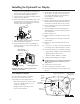
4. Determine where the User Display will be
located. The display can be attached to the
water heater jacket with supplied Water Heater
Mounting Bracket or mounted remotely to a
wall via the wall plate up to 100 feet away
using 18 AWG solid copper thermostat wire.
Any installation location over 12 feet from the
water heater will require additional thermostat
wire. (Not supplied.)
5. If remote mounting, go to step 19.
6. Cut enough thermostat wire from the 12 feet
provided to connect the front mounted display
to the Transformer Enclosure located on the top
pan.
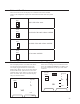
7. Strip ½ in. insulation from the 3 wires on both
ends. The wire provided is standard 3-wire with
the colors GREEN, RED and WHITE.
8. Connect one end of the wire to the Transformer
Enclosure spring terminal strip. From left to
right colors shall be GREEN – RED – WHITE.
Wires should easily insert into the terminal
strip. If required for wire insertion or removal,
use small flat blade screw driver to press the
tab located below each wire hole.
9. Remove two strips of Display Mounting Tape
and attach to the inside flanges of the Water
Heater Mounting Bracket.
Transformer
Pin Plug
Six (6) Pin Connection for
to Circuit Board
Mounting Holes for
Transformer
Display Mounting
Tape Strips
Water Heater
Mounting Bracket
for Display
Flange of Mounting
Bracket