
Owner manual

Series RMA-B close-coupled design Page 11
9475-055-en Revision 14
TM 8256 Edition 06/2011
5 Installation
5.1 Safety regulations
Equipment which is operated in potentially
explosive areas must satisfy the explosion
protection regulations.
People with a pacemaker are at risk from the
strong magnetic field of the magnetic drive. It
may be life-threatening for them to stay at a
distance of less than 20” (500 mm) to the
pump.
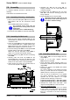
5.2 Installation of pump/unit
The structural work must be prepared in accordance
with the dimensions in the installation drawing.
Method of installation: on a grouted base plate and
firm foundation
Align base plate on the ground foundation.
Insert foundation bolts and grout base plate.
Do not tighten the foundation bolts uniformly and
firmly until the mortar has set.
Other possibilities of installing the pump are:
4-point installation
4-point installation with base plate.
As soon as additional installations are
mounted, the stability of the entire unit
installed without a foundation must be
checked.
5.3 Alignment of pump - motor
The following information is of a general
nature. If necessary, special notes of the
coupling and motor manufacturer are to be
observed.
Before starting alignment, undo the screw fitting of
the support bracket from the adapter and motor.
Align the unit with the housing so that there is no
tension and retighten the screws.
Use supports in the direct vicinity of the bolts
foundation/base plate.
5.4 Piping
Before the pump is installed, both, the suction and
supply lines as well as the discharge line are to be
cleaned.
Dirt or damage to the sealing surfaces is best avoided
if the flange covers remain on the flanges until just
before installation.
Use flange gaskets suitable for the medium.
The screw tightening torques in Chapter 1.1
are to be
observed for tightening the flange screws.
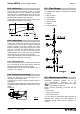
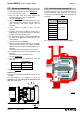
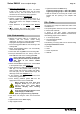
5.4.1 Nominal size
T
he operating design point of a centrifugal pump lies
at the intersection of the pump curve and the pipe
curve, see Fig. 2. The pump curve is provided by the
pump manufacturer. The pipe curve is determined
using diagrams or PC programs.
Fig. 2
Under no circumstances can the nominal size of the
piping be derived from the connected nominal size of
the pump.
The pipe nominal size can also be determined using
the flow rate as a rough guide.
)ft(Ax449
)gpm(Q
)s/ft(v
2
=
)m(A
)s/m(Q
)s/m(v
2
3
=
The velocity in the suction line should not exceed
6.56 ft/s (2 m/s) and 16.4 ft/s (5 m/s) in the discharge
line.
When determining the suction line nominal size, the
NPSH value (net positive suction head) must also be
observed. The NPSHR value required for the pump
is specified in the data sheet.
The NPSHR available in the plant
should be at least 1,64 ft (0,5 m)
higher than the NPSHR required for
the pump. Otherwise, this will lead to a drop in the
delivery head, cavitation or even failure of the pump.
5.4.2 Nozzle loads
The pump can be subjected to nozzle loads in
accordance with ANSI/HI 9.6.2.
Changes in the length of the piping caused by
temperature are to be allowed for by appropriate
measures, e.g. the installation of expansion joints.