ADDITIONAL INSTALLATION AND OPERATING MANUAL Series MNK, MNK-B ® SAFERUN Pump Condition Monitoring System Keep for future use! This operating manual must be strictly observed before transport, installation, operation and maintenance! Subject to change without notice. Reproduction is generally permitted with indication of the source. © Richter Chemie-Technik GmbH.
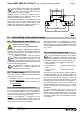
Series MNK, MNK-B, SAFERUN® Pump condition monitoring system Page 2 List of contents List of contents 2 Relevant documents 2 1 About this document 3 1.1 1.2 1.3 1.4 1.5 Manufacturer ............................................... 3 Function ....................................................... 3 Target group ................................................ 3 Symbols used .............................................. 3 Name plate ..................................................
Series MNK, MNK-B, SAFERUN® Pump condition monitoring system 1 About this document The pump can also be put into operation without the pump condition monitoring system being connected. 1.1 1.4 Manufacturer EU Community symbol! Explosionprotected equipment must be marked for work in potentially explosive areas. Note: Some of the functions described here are not available or only to a certain extent in the versions supplied in the pilot phase.
Series MNK, MNK-B, SAFERUN® Pump condition monitoring system 2 Safety 2.1 Authorised personnel 2.5 Page 4 CE conformity ® Actions described in this operating manual may only be performed by trained and skilled personnel authorised by the plant operator. Interventions above and beyond this may only be undertaken by personnel authorised by the manufacturer for safety or warranty reasons. The SAFERUN is CE-compliant with the: 2.
Series MNK, MNK-B, SAFERUN® Pump condition monitoring system 3 Product description 3.1 Function The scope of delivery comprises: ® SAFERUN transformer Note: see Section 1.4. Attachment unit (holding plate with screws) ® SAFERUN can unit The system reports changes in the operating condition permitting conclusions to be drawn about the operation of the pumps in relation to the admissible ranges of operation specified by the manufacturer.
Series MNK, MNK-B, SAFERUN® Pump condition monitoring system SAFERUN® transformer Page 6 3.2.2 Operation The status display and operation of the system can be performed via: 1 5 2 coloured LEDs on site handheld unit (PDA) with suitable radio interface HART protocol the service program via the built-in serial interface (special cable required). 3 6 3.3 4 7 Fig. 4 SAFERUN® can unit 1 Storage and transport ® Standard A: Pump is ordered with SAFERUN .
Series MNK, MNK-B, SAFERUN® Pump condition monitoring system Page 7 Even if all connection points of the system are secured against exceeding the admissible limit values, the connection cable should not be screwed on or off during operation. Optionally, the unit can also be positioned and installed somewhere else to satisfy the needs of the customer (maximum cable length 5m). ® In this case the SAFERUN is installed directly in the plant on site.
Series MNK, MNK-B, SAFERUN® Pump condition monitoring system 5.3 Page 8 Terminal diagram Fig. 7 5.4 Circuit diagram Application in pot. expl. area Application in non-pot. expl. area Power supply 230V AC or 24V DC Power supply 230V AC L+ M- PE L N L+ M- PE PE U1 U=230V AC od. 24V DC P=2,4W OO+ V+ O- 4..20mV output NON-HART and HART possible O+ V+ I+ Non-pot. expl. area 4..20mV output NON-HART and HART possible I+ shielded shielded Pot. expl. area Input max.
Series MNK, MNK-B, SAFERUN® Pump condition monitoring system 6 Page 9 Commissioning with the integrated display and control unit The system is tested and subjected to basic calibration as standard ex works together with the relevant pump. Tap water is used as the medium conveyed. ® Standard A: MNK with SAFERUN can insert without transformer ® Standard B: with SAFERUN order incl.
Series MNK, MNK-B, SAFERUN® Pump condition monitoring system 6.2 Condition monitoring and event display Note: see Section 1.4. The monitoring mode is the normal mode of the ® SAFERUN . In this mode the following conditions can be detected and displayed by the system: Operation within the recommended operating limits: Direction of rotation: Is determined every time the pump is put into operation.
Series MNK, MNK-B, SAFERUN® Pump condition monitoring system 6.2.2 Loading parameters Load parame- RFID Error FRAM Error DEFAULT SERVICE MODE Copy FRAM parameters into RFID Copy FRAM parameters into RFID Operating mo- 6.2.3 Legend of designations RAM ROM CLOCK FRAM RFID Main memory Contains firmware Current time Non-volatile memory for parameters and event logger Non-volatile memory for parameters and data logger 6.2.4 Event display Note: see Section 1.4.
Series MNK, MNK-B, SAFERUN® Pump condition monitoring system Page 12 6.2.5 Normal operation with density known LED 9230-070-en TM 7691 mA to % to % diff. 93.75 100.00 6.25 19 87.50 93.75 6.25 14 18 62.50 87.50 25.00 2/3 10 14 37.50 62.50 25.00 4% Qmax+Qmin 1/3 6 10 12.50 37.50 25.00 Qmin 4% Qmax+Qmin 5 6 6.25 12.50 6.25 Qzero Qmin 4 5 0.00 6.25 6.25 Pump standstill Qzero Range from Range to mA from 0.8x MdMax drive stoppage 20 1.04 Qmax 0.
Series MNK, MNK-B, SAFERUN® Pump condition monitoring system Page 13 6.2.6 Customer operation with density known Range from Range to mA from mA to % from 0.8x MdMax Drive stoppage 20 21 100.00 0.04x Qmax+KdMax 0.8 MdMax 19 20 KdMax 0.04x Qmax+KdMax 18 2/3 KdMax 1/3 LED 9230-070-en TM 7691 % to % diff. 93.75 100.00 6.25 19 87.50 93.75 6.25 14 18 62.50 87.50 25.00 2/3 10 14 37.50 62.50 25.00 KdMin 1/3 6 10 12.50 37.50 25.00 KdMin-4% Qmax KdMin 5 6 6.
Series MNK, MNK-B, SAFERUN® Pump condition monitoring system Page 14 6.2.7 Customer operation with unknown media LED % to % diff. 93.75 100.00 6.25 19 87.50 93.75 6.25 14 18 62.50 87.50 25.00 2/3 10 14 37.50 62.50 25.00 KdMin 1/3 6 10 12.50 37.50 25.00 KdMin-4% (PmaxP0) KdMin 5 6 6.25 12.50 6.25 KdMin-8% (PmaxP0) KdMin-4% (PmaxP0) 4 5 0.00 6.25 6.25 Pump standstill KdMin-8% (PmaxP0) Range to mA from 0.8x MdMax Drive stoppage 20 0.04x Qmax+KdMax 0.
Series MNK, MNK-B, SAFERUN® Pump condition monitoring system 7 Maintenance and fault rectification 7.1 Maintenance Page 15 ® The SAFERUN does not require any special maintenance if used correctly in normal operation. 7.2 Fault rectification Note see Section 1.4 For description, see Fig. 9 and Section 6.2.3. Software diagnosis Hardware diagnosis Self test RAM A flashes Manuf. ROM B flashes Firmware new CLOCK C flashes Manuf. FRAM D flashes Manuf.
Series MNK, MNK-B, SAFERUN® Pump condition monitoring system 7.3 Page 16 Repairing the unit ® The SAFERUN may only be repaired by the manufacturer, Richter Chemie-Technik. If it is necessary to replace individual electronic components, e.g. back plate or flat-ribbon cable, this may be only done if replaced by original spare parts from Richter Chemie-Technik; under certain circumstances recalibration may become necessary.
Series MNK, MNK-B, SAFERUN® Pump condition monitoring system 9 Annex 9.1 Technical specifications Page 17 GENERAL DATA Manufacturer Unit Type Technical documentation Design IP protection class (EN 60529) Housing material Tension spring terminals Richter Chemie-Technik GmbH Condition monitoring system 4764-19-0020/02 BTA 9230-020-de. Unit for mounting on pumps or for wall mounting (cable of special length required) IP 65 6 ABS, modified (surface resistance 10 ) 2 Max. line cross section 1.
Series MNK, MNK-B, SAFERUN® Pump condition monitoring system 9.2 Page 18 Dimensions Fig. 10 9.3 Industrial property rights Products of Richter Chemie-Technik are subject to industrial property and patent rights. 9.4 Trademarks All trademarks used as well as trade and company names are the property of their legal owners/authors.