Operation Manual 1. Before Use 2. Basic Operations 3. Extended Functions 4. Maintenance 5. Troubleshooting 6. Appendix Original instructions This manual contains detailed instructions and notes on the operation and use of this product. For your safety and benefit, read this manual carefully before using the product.
TABLE OF CONTENTS Information ........................................................................... v Introduction ...................................................................... v Legal Prohibition .............................................................. v CAUTION ............................................................................ vi DISCLAIMER OF WARRANTY .......................................vi FCC Statement (USA) .....................................................
Chapter 2 Basic Operations Workflow ........................................................................... 2-2 Turning the Power ON/OFF .............................................. 2-3 Turning the Power ON ......................................................2-3 Turning the Power OFF ....................................................2-4 Setting a Media ................................................................. 2-5 Adjusting the Head Height ................................................
Setting nozzle face cleaning time ......................................3-8 Other Settings ...................................................................3-9 Machine Settings .............................................................3-10 Setting a AUTO Power-off .............................................. 3-11 Setting the Display of Media Residual ............................ 3-12 Setting Time ................................................................... 3-14 Setting Units ..................
Chapter 5 Troubleshooting Troubleshooting ................................................................ 5-2 Power does not turn on .....................................................5-2 The machine does not start printing .................................5-2 Media get jammed / media is soiled .................................5-3 [HEAT] or [CONSTANT] LED does not light up ................5-4 Image quality is poor .........................................................5-4 Nozzle is clogged ............
Information Introduction Read this manual carefully before you use this machine and keep it handy for future reference. For safe and correct use, be sure to read the Safety Precautions in this manual before using the machine. Legal Prohibition Do not copy or print any item for which reproduction is prohibited by law. Copying or printing the following items is generally prohibited by local law: bank notes, revenue stamps, bonds, stock certificates, bank drafts, checks, passports, driver's licenses.
CAUTION DISCLAIMER OF WARRANTY Contents of this manual are subject to change without prior notice. To the maximum extent permitted by applicable laws, in no event will the manufacturer be liable for any damages whatsoever arising out of failures of this machine, losses of the registered data, or the use of this product and operation manuals provided with it. Make sure that you always copy or have backups of the data registered in this machine.
For Users in India This product complies with the "India E-waste Rule 2011" and prohibits use of lead, mercury, hexavalent chromium, polybrominated biphenyls or polybrominated diphenyl ethers in concentrations exceeding 0.1 weight % and 0.01 weight % for cadmium, except for the exemptions set in Schedule 2 of the Rule.
CAUTION DECLARATION OF CONFORMITY We, RICOH CO., Ltd. at address 3-6, Naka-magome 1-Chome, Ohta-Ku, Tokyo 143-8555, Japan declare under our sole responsibility that the product consisting of the following; Product Name : Model Name : Inkjet Printer Pro L4160, Pro L4130 to which this declaration relates is in conformity with the following standards.
Safety Precautions Symbols Symbols are used in this Operation Manual for safe operation and for prevention of damage to the machine. The indicated sign is different depending on the content of caution. Symbols and their meanings are given below. Please follow these instructions as you read this manual. Examples of symbols Meaning Failure to observe the instructions given with this symbol can result in death or serious injuries to personnel. Be sure to read it carefully and use it properly.
Safety Precautions Warning for Use WARNING • The set of power cables provided with this machine is for use with this machine only, and cannot be used with other electrical devices. Do not use any power cables other than the ones provided with the machine. Failure to observe those instructions may result in fire or electric shocks. • Take care not to damage, break or work upon the power cable.
CAUTION Handling of the power cable • Connect to a socket-outlet with determinate polarity. • For Inlet 1 and 2, be sure to supply power from the outlet of the same voltage. • for PLUGGABLE EQUIPMENT, the socketoutlet shall be installed near the equipment and shall be easily accessible. • Unplug the cord from the wall outlet and remove dust from the power plug periodically, at least once a year. Failure to do so may result in fire or electric shocks.
Safety Precautions CAUTION Notes on Handling the Machine • Do not use the machine in a confined or poorly ventilated room. • Keep the room well ventilated when using the machine. • Do not use the machine under humid or dusty environment. Doing so may result in fire or electric shocks. • Do not place the machine on unstable or inclined surface. The machine may fall or topple over and cause a damage or injury. • There is a cutter inside the machine for cutting print media.
CAUTIONS and NOTES Warning Handling of ink cartridges Front cover and lever • The safety evaluation of this machine assumes that the ink recommended by this company is used. For safe usage of this machine, use the ink recommend by this company • Never refill the ink pack and white ink cartridge with ink. Refilled ink cartridge can cause a trouble. Remember that RICOH assumes no responsibility for any damage caused by the use of the ink cartridge replenished with ink.
Safety Precautions Cautions on Installation CAUTION A place sunlight exposed to direct On an inclined surface A place where temperature or humidity varies significantly • Use the machine under the following environmental conditions: • Operating environment: 20 to 30 °C (68 to 95 °F) 35 to 65 % (Rh) A place that vibrates A place exposed to direct air flow from an air conditioner or the like.
Safety Precautions Safety interlock This machine is equipped with interlocks to terminate the operation for your safety when the cover opens during printing etc. (red circle parts in the figure below).
Warning labels Warning labels are stuck on the machine. Be sure to fully understand the warning given on the labels.
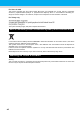
Warning labels No. Always follow the procedure described in this manual when loading and replacing paper, removing jammed paper, cleaning the media transfer surface, and performing any other operations inside the machine. Otherwise, the carriage may hit or catch your hand and cause injury. 1 2 2 3 4 5 5 Always wear the goggle and gloves provided with this machine to prevent your skin to come in contact with the cleaning fluid when cleaning the ink station and print head.
Chapter 1 Before Use This chapter describes the items required to understand before use, such as the name of each part of the machine or the installation procedures. Moving This Machine .................................... 1-2 Where to Install This Machine ..................... 1-2 Working Environmental Temperature ......... 1-2 Moving This Machine .................................. 1-2 Names of Parts and Functions ...................... 1-3 Front Side of the Machine ...........................
Moving This Machine Where to Install This Machine Secure a suitable installation space before assembling this machine. The place of installation must have enough space for not only this machine itself, but also for the printing operation.
Names of Parts and Functions Front Side of the Machine Left maintenance cover Front cover Open the cover in maintenance. Even when the power switch is off, keep all covers closed. Open the cover in setting of medias, taking of measures against jamming of medias or in maintenance inside the station. Even when the power switch is off, keep this cover and the other covers closed. Ink cartridge setting section Set the ink cartridge for each color.
Rear Side and Right Side of the Machine Pre-heater Clamp lever (rear) Interlocks with the clamp lever in the font of this machine. Preheats the media before printing. (Located inside the Media Transfer Surface) Cleaning solution cartridge Set a Washings cartridge that is recommended by this company. W filter maintenance cover Cover for white filter maintenance. Roll holders Putting this into the paper core (right and left) of a narrow roll medium (less than 1.6m), hold the medium.
Names of Parts and Functions Operation Panel Use the operation panel to make settings for printing or operate this machine. Display Displays the status of the machine, set items and errors. CONSTANT lamp Lights in green when the heater temperature reaches the set temperature. HEAT lamp Lights in orange during heating up of the heater. ACTIVE lamp It lights when the power supply is turned on. key 1 Use this key on cutting . MAINT. key Performs the maintenance function such as station maintenance.
Heater Pre-heater/Print heater/Post-heater are equipped on the Media Transfer Surface. The Pre-heater is used for pre-heating of the media prior to printing to prevent rapid changes in temperature. The Print-heater improves the image quality in printing.The Post-heater and drying-heater dries ink after printing. • While the heater is on, the Media Transfer Surface is very hot.
Names of Parts and Functions Carriage The carriage is provided with the heads for printing, the cutter unit for cutting off the sheet of media, etc. A lever is also provided to adjust the height of Head in 3 stages according to the thickness of media. ( P.2-5) Carriage 1 Before Use Cutter blade and slot for cutting The carriage is provided with a cutter unit for cutting off the media that has been printed on.
Connector of Temperature sensor/ Drying heater/ Take-up device Connector of Temperature sensor/ Drying heater/ Take-up device If an error related to the Temperature sensor/ Drying heater/ Take-up device occurs, refer to the Chapter 5 and check the connector. Temperature sensor (red) Drying heater (blue) Take-up device (black) Capping station • Be sure to wear the attached goggles in cleaning within the capping station to protect your eyes against ink. Otherwise, you may get ink in your eyes.
Names of Parts and Functions Pinch rollers and Feed rollers • Keep the pinch rollers lifted up when this machine is not in use. If the pinch rollers are left lowered for an extended period of time, they can be deformed and fail to securely retain the media. This machine retains the media with the pinch rollers and feed rollers. During printing operation, the feed rollers feed the media forward.
Connecting Cables Connecting USB2.0 Interface Cable Connect the PC and this machine with the USB2.0 interface cable. USB cable • Your RIP must be compatible with USB 2.0. • When you connect USB cable, do not touch the connector contact point with your bare hand. Static may be generated and it may break the PCB of this machine. Notes on USB 2.0 Interface • Your RIP must be compatible with USB 2.0.
Connecting Cables z Removing USB memory If a USB memory module is inserted in the personal computer to which a Pro L4160/L4130 machine is connected, click "Stop" in the "Safely Remove Hardware" window by following the instructions given there first and then remove the module. Leaving a USB memory module inserted can cause [ERROR 201 COMMAND ERROR]. Copy the data onto the hard disk before outputting it for printing.
Inserting ink cartridge Insert an ink cartridges. How to assemble ink cartridge Before setting the ink cartridge, it is required to set the ink pack on the eco cartridge. By following the next procedures, assemble the ink cartridge. 1 Open the cover of the eco cartridge. (1) Press the center part of the cover with your finger. • The claw on the side without attaching part of IC chip comes off. Press the center part with your finger. (2) Raise the cover as described in the photo.
Inserting ink cartridge (2) Peel the seal of double coated tape. 3 Firmly fix the ink pack on the eco case with double coated tape so that it may not move. • Fix the ink pack after pulling it so that the ink pack may not go slack. 1 Before Use • Fix the ink pack so that it may not be biased in the eco case. Good example The corner of the case matches the ink pack corner. 4 Attach the cover. 5 Attach the IC chip. Bad example The ink pack has gone too far downward.
About the ink that can be used with this machine The following three types of ink sets can be used with this machine: 4 color, 6 color, and 6 color+white versions • 4-color version: 2 each of Cyan, Magenta, Yellow and Black ink cartridges are used. • 6-color version: 1 each of Yellow, Orange, Green, and Black, 2 each of Cyan and Magenta ink cartridges are used. • 6-color+white version: 1 each of Cyan, Magenta, Yellow, Orange, Green and Black, and 2 White ink cartridges are used.
Inserting ink cartridge 2 Insert the ink cartridge. • Insert the ink cartridge lengthwise with the surface having IC chips pointing to the left side. 1 Setting orders of ink cartridges Before Use The orders of ink cartridges set in the ink station differ depending on the ink set you use. • Set the ink cartridge according to the cartridge label under the ink station.
Changing an ink cartridge Perform as follows when [INK END] or [INK NEAR END] is displayed on the display. z When [INK END] is displayed (1) Pull out an ink cartridge to be replaced. (2) Insert a new ink cartridge, paying attention to the direction of IC chip. z When [INK NEAR END] is displayed There is a little of ink left. It is recommended to replace the ink cartridge soon since ink may become empty in printing while printing is continuously enabled.
Inserting ink cartridge Caution in handling of ink cartridges 1 Before Use • If you get ink in your eyes, immediately wash your eyes with a lot of clean running water for at least 15 minutes. In doing so, also wash the eyess to rinse ink away completely. Then, consult a doctor as soon as possible. • Depending on how the machine is used, the [INK END] message may be displayed even if the [INK NEAR END] message is not yet displayed.
Media Usable media sizes and notes for handling are described. Usable sizes of media Model Pro L4130 Pro L4160 Thin coat paper/PET/Tarpaulin/Weatherproof PVC/Polyester cloth/ Cotton Maximum width 1371mm Minimum width 210mm Maximum printing width 1361mm Roll media Type of Recommended media 1620mm 1610mm *1 Thickness 0.
About antistatic sheet Pro L4130: three antistatic sheets, Pro L4160: four antistatic sheets are attached in this machine. The electrostatic sheet is used to prevent the media from clinging due to static. Use this when static or deflection of the media on the post heater occurs and affects the media feeding. z Fix the electrostatic sheet Hang the claw of the antistatic sheet on the groove of the Media Transfer Surface.
About antistatic sheet If you removed the antistatic sheet, attach the sheet holder on the Media Transfer Surface (Pro L4130: three positions / Pro L4160:four positions). If you do not attach the sheet holder, the heater temperature drops and drying may become not enough.
Chapter 2 Basic Operations This chapter describes procedures and setting methods for ink and media preparation, and printing. Workflow ....................................................... 2-2 Turning the Power ON/OFF .......................... 2-3 Turning the Power ON ................................ 2-3 Turning the Power OFF ............................... 2-4 Setting a Media ............................................. 2-5 Adjusting the Head Height ..........................
Workflow 1 2 3 4 5 6 7 2-2 Turning the Power ON/OFF Referring to “Turning the Power ON/OFF” ( P.2-3). Setting a Media Referring to “Setting a Media” ( Preparing for the Heaters Referring to “Preparing for the Heaters” ( P.2-17). Test Printing Referring to “Test Printing” ( Set the media feeding Referring to “Set the media feeding” ( Correct the ink drop position for bidirectional printing Referring to “Correct the ink drop position for bidirectional printing” ( P.2-25).
Turning the Power ON/OFF Turning the Power ON This machine is provided with the following two power switches: Main power switch:Two switches are located on the side of this machine.Keep this switch ON all the time. Power switch : Normally, use this switch to turn the power ON/OFF. The power switch lights in green when the power is ON. 1 Turn the main power switch ON. 2 Turn the power switch ON. • Set the two main power switches located on the side of this machine to the “I” side.
Turning the Power ON/OFF Turning the Power OFF When having ended the operation of the machine, turn the power OFF by pressing the power switch located on the front side. Check the following items when turning the power OFF. • If the machine is receiving data from the PC or if there is any data that has not been output yet • If the head has returned to the capping station • If any error has occurred ( P.5-14 “Error messages”) 1 Turn OFF the power of the connected PC.
Setting a Media This machine can be used with a roll media and leaf media. For usable medias, refer to P.1-18 “Usable sizes of media”. Adjusting the Head Height Adjust the head height according to the thickness of the media you use. • Turn OFF heater and perform this after temperature dropped. • Adjust the head height prior to setting the media.If the head height is adjusted after the media is set, this may cause a media jamming, deterioration of the print quality or head damage.
4 Fix the carriage. • Fastening the screw in front, you can fix the carriage. • Fasten the screw securely. Fix the carriage. 5 Return the carriage to the station position. • When the power supply is off, return the carriage to the station manually. • When the power supply is on, press the key if the screen below is displayed. S T A T I ON COMP L E T ED 6 2-6 Close the front cover.
Setting a Media Note for media setting When setting media, read the following notes carefully. • Take care not to drop the media on a foot or so when the media is set. It may cause an injury due to the media. • There is a cutter inside the machine for cutting the print media. Do not touch any parts other than the ones described in this manual when loading and replacing paper, removing jammed paper, and cleaning the media transfer surface.
Setting a roll media 1 Roll holder Move the roll holder located in the back of the device to the direction of the middle of the device. • Loosen the roll holder fixing screw and then move it. Roll holder fixing screw 2 Check the clamp lever located in the back of the device is lowered. 3 Move the roll holder to the roll setting position. Roll holder Set the base position of roll holder within this range.
Setting a Media 4 Tighten the roll holder fixing screw. 5 Set the left end of the core of the roll media on the left roll holder. 6 Loosen the screw of the right side roll holder then insert the holder into the core of the roll media. 7 8 Tighten the screw of the roll holder 9 Insert the roll media in this machine. • Check the Step 2 to 3 again. • Push the roll media onto the roll holder until the roll core is all the way seated.
10 Pull out the roll media out. (1) Open the front cover. (2) Raise the clamp lever from the back of this machine. (3) Pull out the roll media gently and then stop pulling when locked lightly. • When setting a medium, be sure to cover the medium sensors located on the rear of the Media Transfer Surface. The media cannot be detected unless it is placed over the sensor. 11 Make the roll media even then lower the clamp lever.
Setting a Media 13 14 Hold the media with the media guide gently. • If the printing result indicates that drying is not enough, use the media guide to improve adhesion of the media to the Media Transfer Surface. • Use the media guide with it hit slightly against the sheet holder. • Make the media pass around the center of the claw of the media guide. Media press Media guide Prepare for the take-up device. 1 Front cover (1) Set an empty core of the roll media on the take-up device.
16 Fix the media on the take-up device. ( P.2-13) (1) Feed the media up to the core of the roll media of the take-up device by pressing the key. • Check the media end is not caught into the slot on the post-heater, and then feed the media. (2) Fix the middle of the media with adhesive tape. (3) In the same manner, fix the left side and right side of the media.
Setting a Media Take-up device With the switch of the take-up device, select the take-up direction of the media or others. Lever in top position (REVERSE) : The take-up device winds the media with the printed side facing in. Lever in middle position (OFF) : The take-up device does not wind the media. Lever in bottom position (FORWARD) : The take-up device winds the media with the printed side facing out.
Setting leaf media Unlike roll media, leaf media does not need to be retained with the roll holders. • After printing, in case that there is not a margin of more than 600mm from the edge, drying feed cannot be fully performed. Therefore, please note that some places cannot pass the drying heater, and drying unevenness and difference in printing quality occur. • Depending on the condition of the media, a media jam may occur.
Setting a Media 6 Hold the media with the media guide gently. • If the printing result indicates that drying is not enough, use the media guide to improve adhesion of the media to the Media Transfer Surface. • Use the media guide with it hit slightly against the sheet holder. • Make the media pass around the center of the claw of the media guide. 7 Close the front cover. 8 Press the 10 1 key. 2 Press the key to select "LEAF" . MED I A S E L EC T RO L L < > L EA F The media detection is started.
Setting a Media Changing the printing origin The position of the printing origin can be changed. Moving the LED pointer to the changing position and deciding the position. 1 In Local, Press 2 Set a light point of the LED pointer to the changing position by pressing . . OR I G I N SE T UP 0.0 - - - - • It enters into the origin setting mode. • Select the carriage and media, moving the point with . • When you press the key here, you can perform media cutting.
Preparing for the Heaters Changing the Temperature Settings for the Heaters Set the heater temperature. Depending on the media and the profile to use, set the heater temperature. • It may take several minutes to tens of minutes for the set temperature to be reached, depending on the ambient temperature. • You can change the temperature set here also in [HEATER] of the [SETUP] menu. ( 1 Press the 2 Press the 3 key. PRE 23 °C P.
Preparing for the Heaters Checking the Heater Temperature 1 Press the 2 Press the key. • The current heater temperature is displayed. PRE 35 °C PR T 40 °C key at the end of confirmation. • The screen returns to LOCAL. Changing the Temperature Settings for the Drying Heater to 1 Press the 2 Press 3 Press the 2-18 key three times. to select a set value. • Set value : OFF / POST setting value+1 to 20°C key to end the setting. • The screen returns to LOCAL.
Test Feeding Since heater is used at high temperature, cockles may occur in some of your media. ( P.5-10) Perform this function before printing, and check whether the media can be fed normally. 1 Press the times. 2 Press the 3 Press key in LOCAL three T E S T F E ED [ EN T ] key. to select ON/OFF. B ACKWARD F E ED : ON B ACKWARD F E ED : ON 1 • When setting "ON", rewind the roll media to take up the slack before printing. 5 Press the 6 Press the key. T E S T F E ED S T AR T key.
Test Printing Print a test pattern to check that there are no discharging defects such as nozzle clogging (slight touching of ink or nozzle missing). Relationship between head row and test pattern The relations between head row and test pattern print position are as follow. Head 1 Head 2 Pattern of head 1 Media advance direction Pattern of head 2 Note on test printing • When using a roll medium, rewind the medium by hand before printing so that it is not loose.
Test Printing Test Printing Print a test pattern to check that there are no discharging defects such as nozzle clogging (slight touching of ink or nozzle missing). In addition, you can select the orientation of the test pattern to print from two types in order to perform test printing repeatedly. Select one depending on your use. 1 : When the set value is "FEED DIR." : When the set value is "SCAN DIR." Media-feeding direction Check before test printing. 2 Press the • Press P.
Head Cleaning About head cleaning Check the printed test pattern result and perform cleaning depending on the status. Select one from the three types below: SOFT : When lines are bent, when any line is missing NORMAL : When any line is missing, when colors are mixed HARD : When poor image quality cannot be improved even by NORMAL or SOFT cleaning Perform head cleaning depending on the test printing result There are three types of head cleaning. Use one by checking the test pattern.
Set the media feeding Correct the feeding rate of media. If the correction value is not appropriate, stripes may appear on the printed image, thus resulting in a poor printing. • When you have changed the media type, check the pattern and perform adjustment depending on the status. • When you have changed the temperature of the heaters, make sure that the [CONSTANT] lamp lights up and that the preset temperature is reached, and then start the correction.
Set the media feeding 6 Press the 7 Press the key. • Print a correction pattern again and check it. • When media correction is needed, perform the operation in Step 5 to make correction. [ EN T ] key several times to end the setting. Performing the station maintenance without You can select “FEED COMP.” by using the Press the key in Local. F E ED COMP . PR I N T Press to select [SETUP]. key key in the Local without pressing the key. Press the key twice.
Correct the ink drop position for bidirectional printing When the condition for printing (media thickness/head height/etc.) has been changed, perform the following operation to correct the ink drop position for bidirectional (Bi) printing and obtain the proper printing result. Example of a Drop Position correct Printed Pattern • The correction pattern for aligning the ink drop position cannot be printed on a media whose width is less than 450 mm. Print quality cannot be guaranteed in such a case.
Correct the ink drop position for bidirectional printing 8 Press the 9 Press the key. • Next test pattern is printed. • Repeat step6 and step7. key several times to end the setting. Performing to correct the dot position without You can select “DROP.POScorrect” by using the key. Press the key in Local. 2-26 Press to select [SETUP], and press the key. key key in the Local without pressing the Press to select [DROP.POScorrect], and press the key twice.
Printing Data Checking the Status of Ink Cartridges Check the status of the ink cartridges before you start printing. If the amount of the remaining ink is low, or the [NEAR END] or [INK END] message is displayed, replace the ink cartridge. • Checking the Ink Cartridges → Displaying the Information of this machine ( • When the ink cartridge is nearly empty • When [NEAR END] warning is displayed • When [INK END] warning is displayed → Changing an ink cartridge ( P.1-16) P.
Starting a Printing Operation • When using a roll media, rewind the media by hand before printing so that it is not loose.When the roll media has not been rewound tightly, it may cause the image quality to deteriorate. • When making a test print, printing the actual image data is recommended. Depending on the image data, you may not be able to achieve the desired image quality. 1 Setting a Media ( 2 Checking the Heater Temperature 3 Press the 4 Transmit data to be printed from the PC. 5 P.
Printing Data Stopping a printing operation halfway Perform the following operation when stopping a printing operation halfway. 1 Press the key during printing. < L OCA L > • The printing operation stops. • Interrupt data sending at the PC side during the data is sent from the PC. • Printing restarts from the interrupted data by repressing the key. w i d t h : 1 2 7 2 mm 1 Deleting Received Data (Data Clear) When you want to stop printing, delete the already received data.
Cutting a media For a roll media, two ways are available to cut the media after printing is completed, as follows. • When a media is cut, be careful that the printed side does not touch the floor or the printed side of other already cut media. • When using the take-up device, take up a cut medium using the switch of the take-up device. 1 Press the 2 Press the 3 Press 4 Press the key. MED I A CU T [ EN T ] key. MED I A CU T CU T POS I T I ON to specify the cutting position. key.
Printing Data When a waste ink bottle confirmation message appears while printing • Printing is canceled, and the current mode returns to LOCAL. • Printing cannot be started while a waste ink bottle confirmation message is being displayed. • In order to resume printing from where it has been paused, clear the waste ink bottle confirmation message. (1) Replace the waste ink bottle with another. ( (2) Press the key. P.
2-32
Chapter 3 Extended Functions This chapter describes the operation procedures for using the machine more conveniently and each setting procedure. List of Functions ............................................ 3-2 Setting Logical Seek ..................................... 3-3 Setting Drying Time ...................................... 3-4 Setting Margins ............................................. 3-5 Perform setting to reduce stripes between passes .........................................................
List of Functions This section describes the overview of each function to be set and set values that can be registered in user types. • About default “HOST” function You can operate this by the setting value specified in RIP software. When you set to other than “HOST”, it operates by that setting value, not by the instruction from RIP software. Depending on RIP software, there are some functions that cannot be instructed by software.
Setting Logical Seek The motion of Head varies depending on the set of Logical-seek. • You cannot specify the logical seek at the RICOH Software RIP side. When you set this machine to “Host”, printing will be performed in “LOGICAL SEEK=OFF” status. • When you set this to “ON” or “HOST” Required time for completion of printing will be shortened. However, enough drying time cannot be ensured and it may affect the image quality.
Setting Drying Time In the drying time setting, the following items for ink drying time are set. • SCAN : Ink drying time for each scanning is set. (During bidirectional printing, the machine stops for a certain period of time specified for each of the outward and return scanning.) • When you give priority to the setting at the RICOH Software RIP side, make the setting value “Host”. • “SCAN” set in this machine is displayed as “Pause Time per Scan” in the RICOH Software RIP.
Setting Margins Set a non-printing area along the right and left edges of the media. The offset value against the standard margin 15mm is set hereupon. • When you give priority to the setting at the RIP software side, make the setting value “Host”. • You cannot specify the margins at the attached RIP software (RICOH Software RIP). When you use the RICOH Software RIP, if you set this machine to “Host”, printing will be performed in “Margins for right and left off set value= 0 mm” status.
Perform setting to reduce stripes between passes In case that feeding stripes cannot be resolved even though media correction ( P.2-23) is performed, make MAPS(Media Advance PassSystem)valid. Feeding stripes become less visible by distributing the pass boundary. • Depending on the printing condition, the effect cannot be recognized. 1 Press the 2 Press the 3 Press 4 Press the 5 Press 6 Press the 7 Press key in LOCAL. key. to select [MAPS]. key. to set ON/OFF. • Set Value : OFF, ON key.
Setting Auto Cleaning You can set items so that the head cleaning is automatically performed when printing has been completed for the set interval. When printing has been completed, the machine count the print count printed after the previous head cleaning and performs the cleaning automatically if necessary. The machine can perform a stable printing operation with its heads always kept clean. The first cleaning is performed immediately before the first printing after the machine is started.
Setting nozzle face cleaning time When the set time has passed, nozzle face of the head is cleaned automatically to remove ink droplets on the nozzle face. In case that deflection, nozzle missing, or symptom which ink droplets fall down occurred, increase the level for each type. If you increase the level, the intervals become shorter. 1 Press the 2 Press the 3 Press 4 Press the 5 Press 6 Press the 7 Press key in LOCAL. key. to select [INTERVAL WIPING]. key. to select types.
Other Settings Change the settings according to the types of use. 1 Press the 2 Press the 3 Press 4 Press the 5 Press 6 Press the 7 Press the key in LOCAL. key. F UNC T I ON S E T UP [ EN T ] S E T UP F E ED COMP . [ EN T ] to select an item for setting. • Select it, referring to P.3-2 “List of Functions”. 1 key. to select the setting value. • Select it, referring to P.3-2 “List of Functions”. 1 key. key several times to end the setting.
Machine Settings Common settings are functions for using this machine easily. The following items can be set in Machine settings. Item Set value Default Meaning AUTO Power-off NONE/ 10 ~ 600min 30min When no operation has been performed for the set time, the power supply is automatically turned “OFF”. MEDIA REMAIN ( P.3-12) ON / OFF OFF You can control the remaining amount of media. TIME +4h ~ -20h Japan time Time difference is corrected. TEMP.
Machine Settings Setting a AUTO Power-off When no operation has been performed for the set time, the power supply is automatically turned “OFF”. 1 Press the 2 Press 3 Press the 4 Press supply. key in LOCAL. to select [MACHINE SETUP]. key twice. to set time to turn OFF the power F UNC T I ON S E T UP [ EN T ] F UNC T I ON MACH I NE SE T UP [ EN T ] AU TO P o w e r - o f f = 3 0m i n AU TO P o w e r - o f f = 6 0m i n • Set Value : none, 10 to 600min 5 Press the 6 Press the key.
Setting the Display of Media Residual Whether the screen displays the remaining amount of a media is set. When the media remaining amount display is turned to "ON" the remaining amount of a media is displayed in Remote. (However, when a leaf media is used, the length of the media to be printed is displayed.) When the media remaining amount display is turned to "OFF" the remaining amount of a media is not displayed in the Remote.
Machine Settings Printing the Remaining Amount of a Media The present remaining amount of a media can be printed. • Set "Remaining amount of a media to display" to "ON". • When you replace the media you use now with another, it is recommended that you print the remaining amount of the media on it.With the remaining amount of a media having been printed beforehand, when you use the replaced media again, you can enter an accurate value in the screen for entering the remaining amount of a media ( P.
Setting Time You can set time of your country (time difference). 1 Press the 2 Press 3 Press the 4 Press 5 Press the 6 Press 7 Press the 8 Press the key in LOCAL. to select [MACHINE SETUP]. key. to select [TIME]. key. [ EN T ] F UNC T I ON MACH I NE SE T UP [ EN T ] MACH I NE SE T UP AU TO P o w e r - o f f [ EN T ] MACH I NE SE T UP T I ME [ EN T ] T I ME 2013 . 10 . 05 21 : 30 : 00 T I ME 2013 . 10 . 05 15 : 30 : 00 to enter time.
Machine Settings Setting Units Units used by this machine are set. 1 Press the key 2 Press 3 Press the 4 Press 5 Press the 6 Press 7 Press the 8 Press 9 Press the 10 Press the in LOCAL. to select [MACHINE SETUP]. key. to select [UNIT]. key. F UNC T I ON S E T UP [ EN T ] F UNC T I ON MACH I NE SE T UP [ EN T ] MACH I NE SE T UP AU TO P o w e r - o f f [ EN T ] MACH I NE SE T UP UN I T [ EN T ] T EMP : °C 1 1 to select a unit of the temperature.
Setting a KEY BUZZER You can turn off the buzzer sound when pressing the key. 1 Press the 2 Press 3 Press the 4 Press 5 Press the 6 Press 7 Press the 8 Press the key in LOCAL. to select [MACHINE SETUP]. key. to select [KEY BUZZER]. key. to select ON/OFF. key.
Machine Settings Setting a LANGUAGE You can change the displayed language. 2 Press 3 Press the 4 Press 5 Press the 6 Press 7 Press the 8 Press the key in LOCAL. to select [MACHINE SETUP]. key. to select [LANGUAGE]. key. to select language. • Set Value: ニホンゴ / English / Deutsch / Français / Español / Italiano / Português key.
Initializing the Settings You can return the setting of “SETUP”, “MAINTENANCE” and “MACHINE SETUP” to the status before shipment. 1 Press the 2 Press 3 Press the 4 Press 5 Press the key. RE SE T A L L S E T T I NG OK ? [ EN T ] 6 Press the key. RE SE T E X ECU T E 7 Press the 3-18 key in LOCAL. to select [MACHINE SETUP]. key. to select [RESET]. • The already configured settings are initialized. key several times to end the setting. • The initial setting screed is displayed.
Confirming Machine Information The information of this machine can be confirmed. The following items can be confirmed as machine information. Item Description WIPING WASTE INK BOTTLE PRINT LENGTH USAGE The information of this machine can be confirmed. PRINT AREA USE TIME FILTER(White) VERSION This displays the firmware version of the machine. LIST This allows you to print the settings of the machine. Ink REPL. Report This prints ink history of this machine.
5 Press the key. • The wiping Information is displayed. • Every time when you press the WIPING Displays wiping information. PRINT LENGTH Displays printed length up to now. WI P I NG = key, the next machine information is displayed sequentially. 0 PR I NT LENGTH = 0m USE TIME Displays used time USE T I ME information of = machine. 0h WASTE INK BOTTLE Displays waste ink WASTE I NK BOTT LE bottle information. = 0% PRINT AREA Displays printed area up to now.
Confirming Machine Information Check such as the machine version information 1 Press the 2 Press 3 Press the 4 Press 5 Press the key in LOCAL. to select [INFORMATION]. key. to select a type of information. F UNC T I ON S E T UP [ EN T ] F UNC T I ON I N FORMA T I ON [ EN T ] I N FORMA T I ON US AGE [ EN T ] I N FORMA T I ON V ERS I ON [ EN T ] MR L - I I I V1 . 0 0 V1 . 8 0 key. • When [VERSION] is selected, the version Information is displayed.
3-22
Chapter 4 Maintenance This chapter describes the items required to use this machine more comfortably, which are the methods for the daily care, the maintenance of the ink unit etc. Maintenance ................................................. 4-2 Precautions for Maintenance ...................... 4-2 About Cleaning Fluid ................................... 4-2 Cleaning the Exterior Surfaces ................... 4-3 Cleaning the Media Transfer Surface .........
Maintenance Maintain the machine regularly or as necessary so that its accuracy will be maintained and it can continue to be used for a long time. Precautions for Maintenance Pay attention to the following items when maintaining this machine. • When using Cleaning Fluid for maintenance, be sure to wear the supplied protective glasses. • The ink contains organic solvent.When cleaning the machine, be sure to wear gloves so that no ink will make direct contact with your skin. • Never disassemble the machine.
Maintenance Cleaning the Exterior Surfaces When the exterior surfaces of the machine are stained, dampen a soft cloth with water or a neutral detergent diluted with water, squeeze it, and wipe the surfaces with the cloth. 1 Cleaning the Media Transfer Surface The Media Transfer Surface easily gets dirty with lint, paper dust, etc. generated when a media is cut. Wipe off conspicuous stains with a soft-hair brush, a dry cloth, a paper towel, etc.
Maintenance Cleaning the Media Sensor The media sensors are located on the Media Transfer Surface in the backside and the bottom surface of the head. When the sensor is covered with dust, etc., it may cause false detection of media. Using a cotton swab, remove the dust, etc. accumulated on the surface of the sensor. When cleaning the sensor on the lower surface of the head is cleaned, move the carriage to the left end by the operations of step 1 of P.
Maintaining the Capping Station Maintain the ink cap, wiper, etc. located in the capping station. (SATION MAINT.) • To keep the nozzle status normal, perform wiper cleaning frequently. • The right message is displayed periodically in LOCAL. When you press the MAINT. key, it moves to cleaning function. WI P ER C L E AN I NG [ MN T ] The ink cap and wiper function as follows. • Wiper : It wipes off ink sticking to the head nozzles. • Ink cap : It prevents the head nozzles from clogging due to dryness.
4 Press the key. • The carriage moves to the maintenance position. • If the carriage is not covered by the ink cap for a long period of time, the nozzle face of the head may get dry and clogged, resulting in white lines being left in the printed image. • The buzzer sounds periodically while the carriage is out of the capping station. The buzzer sounds at shorter interval when the print heater temperature is high. Carriage 5 Open the right maintenance cover cover then remove the wiper.
Maintaining the Capping Station 8 9 10 Clean the wiper slider. • Wipe off the ink sticking of the figure with a clean stick dipped in Cleaning Fluid for maintenance. Wipe off so that Cleaning Fluid for maintenance will not remain. Set the wiper at the original position. Clean Projection 1 • Insert the wiper by holding both ends of the wiper. Clean the area around the wiper.
11 Clean the cap rubber and cap rubber cover. • Wipe off the ink sticking to the cap rubber and cap rubber cover with a clean stick dipped in Cleaning Fluid for maintenance. (Wipe off so that you can see blue color of the cap rubber.) Wipe off so that Cleaning Fluid for maintenance will not remain. Before cleaning Cap rubber After cleaning Cap rubber cover 12 Press the 13 Close the right maintenance cover then press the key. key after the cleaning.
Maintaining the Capping Station 3 Press the 4 Open the right maintenance cover. 5 Fill up the cap with Cleaning Fluid for maintenance. 6 Close the right maintenance cover and press the key. key. • The carriage moves to the maintenance position. • Dry suction operation is performed repeatedly until the washing work is completed.
1 Press the MAINT. 2 Press 3 Press the key in LOCAL. CARR I AGE OU T [ EN T ] to select [CUSTODY WASH]. CUS TODY WA SH [ EN T ] key. • The carriage moves to the maintenance position. • If the carriage is not covered by the ink cap for a long period of time, the nozzle face of the head may get dry and clogged, resulting in white lines being left in the printed image. • The buzzer sounds periodically while the carriage is out of the capping station.
Maintaining the Capping Station 5 Clean the area around the wiper. • Dip the clean stick in the cleaning liquid for maintenance, and wipe the space below the wiper guide, and the space between the wiper slider and ink guard W. Wiper guide Wiper guide Ink guard W Space below the wiper guide Space between the wiper slider and ink guard W 1 Do not clean this part Clean this part along the rail 1 Enlarged view of the Wiper Slider and Ink Guard W 6 Press the key.
Maintaining the Capping Station 8 Press the 9 Fill up the cap with Cleaning Fluid for maintenance. 10 Close the right maintenance cover and press the key. L E AV I NG T I ME = 1m i n Press to set the time for the Cleaning Fluid to be left as it is. L E AV I NG T I ME = 2m i n 11 key. F i l l t he l i qu i d COMP L E T ED ( NEX T ) [ EN T ] • Until washing liquid is filled, [COMPLETED (NEXT): ENT] is displayed on the screen.
Cleaning the Head and the Area around It (every day) Because the head employs a very precise mechanism, due care needs to be taken when it is cleaned. Using a clean stick, etc., rub off gelatinous ink or dust that may stick to the lower part of the slider and the area around the head.In doing so, never rub the nozzles of the head. Tools required for cleaning • Clean stick • Gloves • Goggles • Be sure to wear the attached goggles and gloves when cleaning the area around the head.
Cleaning the Head and the Area around It (every day) 6 Wipe ink sticking to the side of the head off with a clean stick. • To prevent gelled/ solid ink ground from pooling at the front of the carriage, scrape them off with clean stick etc. • Clean the side surface of the head (shown in deep gray) with a clean stick. • Never rub the nozzles. Clean with a clean stick. The nozzle part (Never touch it.) Wipe off the gelatinous or solid ink residue.
Replacing method of absorber kit If ink adheres to the absorber, it is required to replace the absorber. Rough guide for replacement: Replace when the concavity and convexity of the surface of the absorber are filled with ink as indicated in the right photo. In addition, when you replace the absorber, clean ink adhering to the capping station at the same time. • To replace the absorber, the absorber kit separately sold is required. Contact a distributor in your district or our office for purchasing it.
Replacing method of absorber kit 7 Press the 8 Close the right maintenance cover then press the 4-16 key after the cleaning. • After its initial operation, the machine returns to step1. Cl ose cove r COMP L E T ED key.
When Nozzle Clogging Cannot Be Solved When nozzle clogging cannot be solved even after the head cleaning ( following two functions: P.2-22) has been done, perform the NOZZLE WASH • Wash the head nozzle. ( Washing nozzle surface • Wash the nozzle surface. ( NOZZLE RECOVERY • Alternative nozzles for printing, when nozzles missing can not be improved. ( P.4-22) P.4-17) P.4-20) Washing of Head nozzle Perform cleaning of the nozzles in the heads to prevent them being clogged with coagulated ink.
5 Clean the area around the wiper. • Dip the clean stick in the cleaning liquid for maintenance, and wipe the space below the wiper guide, and the space between the wiper slider and ink guard W. Wiper guide Wiper guide Ink guard W Space below the wiper guide Space between the wiper slider and ink guard W Do not clean this part Clean this part along the rail Enlarged view of the Wiper Slider and Ink Guard W 6 Press the key. • The carriage moves onto the Media Transfer Surface.
When Nozzle Clogging Cannot Be Solved 8 Press the key. F i l l t he l i qu i d COMP L E T ED ( NEX T ) [ EN T ] • Until washing liquid is filled, [COMPLETED (NEXT): ENT] is displayed on the screen. After the work up to the Step 8 is completed and you close the right maintenance cover, press the key. If you press the key before washing liquid is filled, the carriage returns to the original position.
Washing nozzle surface Using dedicated washing liquid and a waste cloth, clean the nozzle surface of the head. • Perform this if discharging defect such as nozzle clogging (slight touching of ink or nozzle missing) cannot be improved even if you performed head cleaning ( P.2-22) and nozzle washing ( P.417). Tools required for Maintenance • Maintenance kit • Gloves • When you usually use photographic fixer, do not leave Wiper for CR in a room filled with vapor of photographic fixer.
When Nozzle Clogging Cannot Be Solved 5 Open the left maintenance cover. (1) Turn four screws that fix the maintenance cover to the left, and remove them. (2) Remove the maintenance cover. Rotate it left. Screw • If the maintenance cover is hard to remove, use the Maintenance supplied screwdriver. cover Screw 6 Immerse Wiper for CR in Maintenance kit. 7 Wipe the nozzle surface from the rear of the main body to the front twice or three times with Wiper for CR immersed in Maintenance kit.
Alternative nozzles for printing, when nozzles missing can not be improved NOZZLE RECOVERY: When nozzles missing can not be improved at specific points, other good nozzles can be used as alternatives for printing. 1 Select [NOZZLE RECOVERY] of the maintenance menu. (1) Press the (2) Press (3) Press (4) Press the 2 key in LOCAL. to select [MAINTENANCE] and press the to select [NOZZLE RECOVERY]. key. Select the [PRINT] by pressing press key. key. key.
When Nozzle Clogging Cannot Be Solved 5 Register the Nozzle number that needs NOZZLE RECOVERY and then press key. H1 - A No . 1 : 1 8 4 (1) Select the registration number from 1 to 10 by pressing key and press the . Recovery nozzle No.: or OFF (2) Register the nozzle number that needs recovery by pressing key and press the . Registration number: • Check is performed at the same time of the registration.
When Nozzle Clogging Cannot Be Solved 2 Select the [CHECK] by pressing 3 Press the key. NOZ Z L E RECOVERY : CHECK Level at printing white layer key. • The mode for which nozzle recovery is invalid is displayed. • If there is no mode for which nozzle recovery is invalid, “NONE” is displayed. UNRECOV ERA B L E COND . : 1200x1200 24p /H Lv1 Scanning speed Resolution 4 Press Number of passes the key several times to end the setting.
Automatic Maintenance Function To use this machine comfortably, you can set various maintenances to be performed automatically. Here, set performing intervals of various automatic maintenances. You can prevent troubles such as ink clogging by performing automatic maintenance periodically (automatic maintenance function).
Setting the Cleaning Intervals The cleaning type and the interval between each cleaning operation are set. 1 Select [AUTO MAINT.] of the maintenance menu. 2 Press 3 Press the 4 Press to set the interval between each cleaning operation. (1) Press the (2) Press (3) Press (4) Press the key in LOCAL. to select [MAINTENANCE] and press the to select [AUTO MAINT.]. key. to select [CLEANING]. key. key. AU TO MA I N T . C L EAN I NG [ EN T ] C L EAN I NG : Lv . 1 C L EAN I NG : Lv .
Automatic Maintenance Function Setting the Cleaning Intervals Set the cleaning type and intervals for cleaning of white ink. 1 Select [AUTO MAINT.] of the maintenance menu. 2 Press 3 Press the 4 Press to set the interval between each cleaning operation. (1) Press the (2) Press (3) Press (4) Press the key in LOCAL. to select [MAINTENANCE] and press the to select [AUTO MAINT.]. key. to select [CLEANING(White)]. key. key. AU TO MA I N T .
Replacing consumables Replacing the wiper The wiper is consumable.When the display indicates that it is necessary to check and replace the wiper, immediately replace the wiper with a new one. Also, wipe ink sticking to the lower surface of the slider off. < L OCA L > RE P L ACE WI P ER [ M N T ] • When the warning message for replacing wiper is shown, confirm whether there is no damage and fuzz at the top edge of the wiper film.
Replacing consumables If a Waste Ink Bottle Confirmation Message Appears Ink used in head cleaning, etc. is stored in the waste ink bottle on the lower right side of the machine.This machine counts the accumulated amount of discharged ink. When that reaches a specified amount, the machine displays a confirmation message.(When this message is displayed, consider the replacement of the waste ink bottle.) • The message is displayed when it reaches 80% (1.6L ) of the 2L bottle.
Replace the waste ink bottle with another 1 The message on the right is displayed. 2 Press the MAINT. ink bottle 3 Press the waste ink bottle guard downward to open to the front. < L OCA L > Ch e c k wa s t e key and check the state of the waste Co n f i r m a wa s t e b o t t L e v e l : 8 0%( 1 . 6 L ) Waste ink bottle guard Press downward and pull it 4 Pull it frontward to remove by holding the waste ink bottle handle. Waste ink bottle • Put a cap on the waste ink bottle removed.
Replacing consumables 6 Close the waste ink bottle guard. 7 Press the key. • The ink discharging amount that is controlled by the machine is reset and the message is cancelled.
Replacing the Cutter Blade The cutter blade is consumable.When the cutter blade gets dull, replace it with a new one that is recommended by this company. • The blade is sharp.Be careful not to hurt yourself or anyone else. • Store the cutter blade in a place that is out of the reach of children.In addition, dispose of used cutter blades according to regional laws and regulations. • When replacing the cutter blade, it is recommended to place a sheet of paper under the cutter blade.
Replacing consumables 6 Replace the cutter unit by the carriage. (1) Loosen the screw of the cutter unit. (2) Remove the cutter unit. (3) Mount a new cutter unit. (4) Fasten the screw of the cutter unit to secure the cutter unit. Screw 1 Cutter unit 7 Close the right maintenance cover. 8 Press the 1 key. • The screen returns to step1.
Replacing the white ink filter To prevent nozzle missing due to clogging on the filter, replace the white ink filter periodically. For replacing the white ink filter, the W filter kit sold separately is required. Tool required for • W filter kit replacement work • Gloves • Flat-blade screwdriver • Paper towel • Goggles • The W filter kit is sold separately. Contact a distributor in your district or our office. • Before replacing the white ink filter, check the W filter kit.
Replacing consumables When white ink filter replacing time message is displayed When time to replace the white ink filter has come, the white ink filter replacing message is displayed. 1 The message to inform you of time to replace the white ink filter is displayed. 2 Replace the white ink filter. 3 Fill up the white ink. 4 Clear the white ink filter used days.
If nozzle missing cannot be solved even if you performed white maintenance When nozzle missing of white ink cannot be improved even if you performed white maintenance, replace the filter. 1 Replace the white ink filter. 2 Fill up the white ink. 3 Clear the white ink filter used days. 4-36 • Referring to P.4-29 “Confirmation Message in LOCAL”, replace the white ink filter. • Referring to P.4-38 “Filling the white ink”, fill white ink. • P.
Replacing consumables Replacing the white ink filter Turn off the power supply of the printer and replace the white ink filter. • When replacing the white ink filter, be sure to wear the attached goggles and the gloves. Ink may get in your eyes. • Organic solvent is used for ink. If it adheres to your skin or gets in your eyes, immediately wash off with water enough. 1 Turn OFF the power of the printer. 2 Open the W filter maintenance cover.
Filling the white ink Turn on the power supply of the printer and fill white ink. • When replacing the white ink filter, be sure to wear the attached goggles and the gloves. Ink may get in your eyes. • Organic solvent is used for ink. If it adheres to your skin or gets in your eyes, immediately wash off with water enough. 1 Turn ON the power of the printer. 2 Select [FILL UP INK] of the maintenance menu. 3 Press the 4 Press 5 Press the 6 Open the right maintenance cover.
Replacing consumables 9 Press the key. * * F I L L UP * * P L E A SE WA I T • Ink filling starts. • When ink filling has been completed, the air purge selection screen is displayed. A I R PG END < > S T AR T 10 Press the display. key and show the damper select S E L EC T DAMP ER : MMCC _ _ _ _ 11 Press the _ YKWW]. key and select the damper [ _ _ _ S E L EC T DAMP ER : _ _ _ _ YKWW 12 Press the key. 13 Press the key.
16 Press the key and perform air purge. • Start pushing ink out. (The screen to wait for air purge completion is displayed.) (1) Ink pushed out flows to the jig. (2) Flow ink for about 30 sec. after ink started to flow. (3) After flowing ink for about 30 sec., close the port. (4) Change the jig to another port, flow ink for about 30 sec. in the same way. (5) After flowing ink for about 30 sec., close the port.
Replacing consumables Clearing white ink filter used days Clear the used number of days of the white ink filter to return it to “0” day. 1 Select [USAGE] of the maintenance menu. (1) Press the key in the Local. (2) Select [INFORMATION] by pressing the (3) Select [USAGE] by pressing the • The wiping Information is displayed. keys then press the keys then press the key. key. 2 Press THE key five times, display the used number of days of [FILTER (White)].
4-42
Chapter 5 Troubleshooting This chapter describes the corrective measures to be taken for a phenomenon suspected to be trouble and the procedures to clear the error number displayed on the LCD. Troubleshooting ...............................................................................5-2 Power does not turn on ...................................................................5-2 The machine does not start printing ................................................5-2 Media get jammed / media is soiled .
Troubleshooting Take appropriate actions as described below before taking the trouble as a failure. If still the problem is not solved after troubleshooting, contact your dealer or an office of RICOH. Power does not turn on In most cases, this is due to improper connection of the power cable for the machine or computer. Check that the power cable is connected properly.
Troubleshooting Media get jammed / media is soiled • Do not open or remove the cover or screws other than the ones described in this manual. The machine contains parts that are charged with high voltage and cause electrical-shock hazard. For the checkout, maintenance, or repair of the machine's internal parts, contact your service representative. • Never disassemble or remodel the machine. Doing so may result in fire or electrical-shock hazard.
[HEAT] or [CONSTANT] LED does not light up Check the basic operation. Is the power to the machine ON ? No Turn on the power to the machine. ( P.2-3) Yes Is the heater temperature setting effective ? No Set the heater temperature. ( P.2-17) Image quality is poor This section describes the corrective actions to be taken in case the image quality is not satisfactory. Take remedy for particular problems with image quality. If the remedy does not work, contact your dealer or an office of RICOH.
Troubleshooting Nozzle is clogged When nozzle clogging is not dissolved even after the head cleaning referring to P.2-22, make sure the following operations. Q Wash the head nozzle by the operations of P.4-17. Q Clean the nozzle surface by performing the operations described on P.4-20. Q Recovery the nozzle by the operations of P.4-22. Q Remove air from inside the print head by performing the operations described on P.5-7.
When Error 618 to 61b occur Error 618 to 61b are errors related to the damper. Execute following procedures when an error about damper occurs, or when the nozzle is not unclogged after cleaning. 1 Select [DAMPER] of the maintenance menu. 2 Press the 3 Select the damper to maintenance. 4 Press the 5 Press the (1) Press the (2) Press (3) Press key in LOCAL. to select [MAINTENANCE] and press the to select [DAMPER]. key.
Troubleshooting When nozzle missing occurs due to ink mixture or aeration Push out ink and air in the head from the port. Use this when ink has been mixed in the port, or nozzle missing due to aeration occurs. In addition, if nozzle missing cannot be solved even if you performed cleaning because it has not been used for long time (for about two weeks), perform air purge. 1 Select [AIR PG] of the maintenance menu. 2 Start air purge by pressing the 3 Select the damper to air purge. 4 Press the key.
7 Press the key. • Start pushing ink out. • Flow ink in the jig by 10cm. • Flow ink from all ports of the damper selected in the Step 3. A I R PG COMP L E T ED [ EN T ] Ink Reference value : About 10cm 8 Terminate air purge by pressing the key. • Close the port. CA PP I NG POS I T I ON MOVE S T AR T [ EN T ] • When removing the jig, ink may leak. Put a paper towel etc. around the port. 9 10 5-8 Press the key. • The carriage returns to the cap position. • Filling to the damper starts.
Troubleshooting Regular maintenance of white ink White ink precipitates easier than other inks. • If not printing more than two weeks, white ink may precipitate in the Eco-cartridge or inside of this machine. • When an ink precipitates, the nozzle may be clogged and it can not draw normally. • Make sure to perform periodical maintenance to avoid precipitation and to keep white ink in good condition. • Perform the maintenance below before working once a week. • Use the specified ink cartridge.
Troubleshooting When media heaves up at feeding We call the status of heaving media at feeding “cockling”. When media cockling occurs, check the following items: Note/ checking items Measures Checking media set status (1) Check that the media is set straight and reset it. Adjusting heater temperature (1) Raise the pre-heater temperature by 5 to 10 degrees. (2) Lower all heaters’ temperatures. (When you lower the heater temperature, drying time may not be enough. Lower the FEED SPEED.
Warning / Error Messages If some trouble occurs, the buzzer sounds and the display shows a corresponding error message. Take an appropriate remedy for the displayed error. Warning messages Errors when performing operations Message Cause Solution I N V A L I D O P E R A T I ON CO V E R O P E N The front cover or the maintenance cover is opened. Check the front cover and maintenance covers.
Message Cause Solution The ink of the ink cartridge has been nearly used up. Press the key to check the relevant Eco-cartridge. Be careful because it may be INK NEAR END soon. Ink could not be supplied to the damper. Perform “DAMPER ( P.5-6) ” of the maintenance. Also check the remaining amount of ink in the Eco-cartridge. Even if you performed this, when the message is displayed, contact your local distributor to call for service.
Warning / Error Messages Ink Error Ink error is displayed also in the local guidance. ( Message P.3-21) Cause Solution The IC chip of the ink cartridge cannot be read normally. Remove the Eco-cartridge generating the warning once and install it again. If the same warning message still appears, contact your local distributor to call for service. I NK T YPE : - - - - YYKK The ink of the ink cartridge is different in type from the ink currently supplied.
Error messages When an error message is displayed, eliminate the error according to the chart below. If the same error message appears again, contact your dealer or an office of RICOH to call for service. Message Cause E R ROR 1 0 8 H D CON N E C T [ 1 2 3 4 5 6 7 8 ] Head connection can not be confirmed. E R ROR 1 0 8 H D T H E RM I S [ 1 2 3 4 5 6 7 8 ] Head temperature can not be read. E R ROR 1 0 8 H D MEM EMP [ 1 2 3 4 5 6 7 8 ] The head memory has no data.
Warning / Error Messages Message Cause E R ROR 1 6 e Ma i n PCB V 3 R 3 B An error occurred in the main PCB 3.3VB power supply. E R ROR 1 5 f H E A D D R I V E HO T COM driver becomes the high temperature. E R ROR 1 7 1 N EW H E A D CON N E C T New Print Head was recognized. E R ROR 1 7 2 Ma i n PCB Q6 C h e c k K The main PCB Q6 is disabled (short mode).
Message Cause Solution E R ROR 5 0 5 ME D I A J AM The media jam occurs. Remove the media and reset it. E R ROR 5 0 c ME D I A W I D T H S E N S OR The media width has not been detected correctly. Check the media set position. ( P.28) Clean the media sensor. ( P.4-4) E R ROR 5 0 9 HDC POS CN T A HDC position counter error occurred. E R ROR 5 0 a Y OR I G I N Y-origin could not be detected. E R ROR 5 0 f L - SCA L E B L ACK Abnormal linear scale.
Warning / Error Messages Message Cause Solution There is a slot in which the Eco-cartridge has not been inserted more than a certain time. Set an Eco-cartridge. E R ROR 7 0 2 T H E RM I S T OR CON N E C T The thermistor connection of a heater is defective. Check the thermistor connection of the drying heater. Turn off the main power to the machine and turn it on after a while. If the same error message appears again, contact your local distributor to call for service.
5-18
Chapter 6 Appendix This chapter contains the lists of the specifications and functions of this machine. Specifications ..................................................................................6-2 Machine specifications ....................................................................6-2 Ink specifications .............................................................................6-3 List of consumables .........................................................................
Specifications Machine specifications Item Print head Drawing mode (scan x feed) Pro L4130 Pro L4160 Method Drop-on-demand piezoelectric print heads Specification 2 head 4-color 900x900 : Bi/Uni 6/12/24pass 900x1200 : Bi/Uni 8/16/32pass 1200x900 : Bi/Uni 6/12/24pass 1200x1200 : Bi/Uni 8/16/32pass 6-color 6-color + White 900x900 : Bi/Uni 12/24/48pass 900x1200 : Bi/Uni 16/32/64pass 1200x900 : Bi/Uni 12/24/48pass 1200x1200 : Bi/Uni 16/32/64pass (Depending on the drawing mode, some pass cannot be sel
Specifications Item Recomend ed Environment Pro L4130 Available temp. 20 °C to 30 °C Humidity 35 to 65% Rh (No condensation) Guaranteed temp. 20 °C to 25 °C Pro L4160 Temperature change ± 10 °C / h or less Dust 0.15mg/m3 (Equivalent to normal office level) Highest operation height 2000 m Weight 198 kg 235 kg Outside dimensions 2634 mm(W) x 854 mm(D) x 1435 mm(H) 2879 mm(W) x 854 mm(D) x 1435 mm(H) *1. Some media have bad drying characteristics. Please check this beforehand. *2.
Specifications List of consumables Product name Product code Pro Maintenance kit Type A For North America:841970 For Europe:841973 Pro Cleaning Stick Type A 841909 Product name Pro Filter kit Type A Product code 841912 Product name Product code For North America:841971 For Europe:841974 Pro Flushing Cartridge Type A Product name Prod
Sheet for inquiry Use this sheet for troubles and abnormal functions of the machine. Fill in the following necessary items, and then fax the sheet to our sales office. Company name Person in charge Telephone number Machine model Operating OS Machine information *1 Error message Contents of inquiry Appendix *1. Refer to "Confirming Machine information" of "Convenient using" then fill in necessary information. ( 6 P.
Function Flowchart < L OC A L > WH I D T H : * * * * mm OR I G I N S E T U P 0.0 - - - - ME D I A CU T [ ENT ] PRE 35°C PRT 35 °C T ES T PR I NT ( F EED D I R . ) POS T 35 °C [ ENT ] OR I G I N S E T U P * * OR I G I N * * * * CU T T I NG * * P L E A S E WA I T 35 °C ( 35 °C 35°C 35°C 35 °C 35 °C) * * P R I N T I NG * * P L E A S E WA I T FEED DIR., SCAN DIR. C L E A N I NG TYPE : SO F T SE L ECT HEAD : 12 SOFT, NORMAL, HARD T ES T F EED [ ENT ] B A C KWA RD F E E D : ON ON, OFF MAINT.
Function Flowchart F AN HEA T ER : READY ( 1 0 ° C ) * * C L E A N I NG * * P L E A S E WA I T T ES T F EED [ ENT ] * * T ES T F EED * * P L E A S E WA I T Appendix CU T POS I T I ON 0.
From P.6-6 ADJUST F E E D COMP . [ ENT ] F E E D COMP . PR I NT [ ENT ] ADJUST DROP . POS c o r r e c t [ ENT ] * * * * I NK R EMA I N 6-8 MMCC Y Y K K 99999999 DROP .
Function Flowchart * * P R I N T I NG * * P L E A S E WA I T F E E D COMP . = 0 -9999 to 9999 * * P R I N T I NG * * P L E A S E WA I T P A T T E RN 1 = P A T T E RN 2 = 0.0 WA RN I NG ! Re p l a c e Wi p e r [ MN T ] ME D I A W I D T H = 1 0 0 0 mm MR L - I I I V1 . 00 V1 . 80 NO Z Z L E R E COV E R Y : * CON F I RM D E T A I L S [ MN T ] 0.0 SER I A L N o . : ******** MAINT. H1 - A : * * No . 1 - 5 001 / 00x / - - - / - - - / - - - When there is no recovery, it is not displayed.
< L OC A L > WH I D T H : * * * * mm F UNC T I ON SE TUP [ ENT ] F UNC T I ON MA I N T E N A NC E [ ENT ] F UNC T I ON MA CH I N E S E T U P [ ENT ] F UNC T I ON I N F OMA T I ON [ ENT ] SETUP MAINTENANCE MACHINE SET I N F OMA T I ON U S AGE [ ENT ] I N F OMA T I ON V E R S I ON [ ENT ] I N F OMA T I ON L I ST [ ENT ] I N F OMA T I ON I n k REP L .
Function Flowchart To P.6-12 To P.6-16 To P.6-20 W I P I NG = 0 WA S T E = PR I N T AREA = 0m 2 U S E T I ME = MR L - I I I V1 . 00 V1 . 80 L I ST PR I NT S T ART [ ENT ] I n k REP L .
SETUP SE TUP F E E D COMP . [ ENT ] * * P R I N T I NG * * P L E A S E WA I T SE TUP DROP . POS c o r r e c t [ E N T ] DROP . POS c o r r e c t PR I NT [ ENT ] * * P R I N T I NG * * P L E A S E WA I T SE T UP HE A T ER PRE = [ EN T ] [ ENT ] F E E D COMP .
Function Flowchart F E E D COMP . = Print end . 0 -9999 to 9999 P A T T E RN 1 = Print end 0.0 -40.0 to 40.0 POS T = OF F F AN HEA T ER = POS T + 2 0 ゜C OFF / 20 to 70°C OFF / +0 to 20°C P A T T E RN 2 = 0.0 -40.0 to 40.
From P.
Function Flowchart Displayed when “MANUAL” is set.
MAINTENANCE MA I N T E N A NC E S T A T I ON [ EN T ] S T A T I ON C A RR I AGE OU T [ ENT ] MOV E POS I T I ON S T A T I ON MA I N T . [ ENT ] STATION MAINT. / HEAD MAINT. MA I N T E N A NC E NO Z Z L E R E COV E R Y [ E N T ] S T A T I ON NO Z Z L E WA S H [ ENT ] W I P E R C L E A N I NG COMP L E T E D ( N E X T ) [ E N T ] S T . MA I N T E N A NC E D I SWA Y WA S H [ ENT ] D I SWA Y WA S H COMP L E T E D S T .
Function Flowchart C A RR I AGE OU T COMP L E T E D Cl ose C A P C L E A N I NG COMP L E T E D ( N E X T ) Cl ose cover Cl ose cover C A P C L E A N I NG COMP L E T E D ( N E X T ) Cl ose Cl ose cover [ ENT ] : en t F i l l t he l i qu i d . COMP L E T E D ( N E X T ) : e n t To Local after initializing L E A V I NG T I ME = 1m i n L E A V I NG T I ME = 1m i n Displayed on CLEANING : en t cove r F i l l t he l i qu i d .
From P.6-16 MA I N T E N A NC E A U T O MA I N T . [ EN T ] A U T O MA I N T . RE FRESH [ ENT ] RE F RE SH : Lv . 1 Lv.1, Lv.2, Lv.3 A U T O MA I N T . C L E A N I NG [ ENT ] C L E A N I NG : L EVE L 1 Lv.1, Lv.2, Lv.3 A U T O MA I N T . C L E A N I NG ( Wh i t e ) [ E N T ] C L E A N I NG : L EVE L 1 Lv.1, Lv.2, Lv.
Function Flowchart TYPE : NORMA L NORMAL / SOFT / HARD TYPE : NORMA L NORMAL / SOFT / HARD * * C L E A N I NG * * P L E A S E WA I T * * F I L L UP * * P L E A S E WA I T A I R PG MOV E S T A R T [ ENT ] A I R PG POS I T I ON S T ART [ ENT ] * * F I L L UP * * P L E A S E WA I T A I R PG POS I T I ON MOV E S T A R T [ ENT ] [ ENT ] C A P P I NG POS I T I ON MOV E S T A R T [ EN T ] [ ENT ] > S T ART A I R PG E ND < > S T ART P L E A S E WA I T C A P P I NG POS I T I ON MOV E S T A R T [ ENT
MACHINE SET MA CH I N E S E T U P AU TO P o w e r - o f f [ EN T ] AUTO P o w e r = -of f 3 0m i n none/ 10 to 600min MA CH I N E S E T U P ME D I A R EMA I N [ EN T ] ME D I A R EMA I N : OF F ON / OFF MA CH I N E S E T U P T I ME [ EN T ] T I ME 2011 . 10 . 05 21 : 36 : 00 MA CH I N E S E T U P UN I T [ ENT ] T EMP .
Function Flowchart Appendix 6 6-21
EN GB EN US EN AU M153-7511