350 S. St. Charles St. Jasper, In. 47546 Ph. 812.482.2932 Fax 812.634.6632 www.ridetech.
350 S. St. Charles St. Jasper, In. 47546 Ph. 812.482.2932 Fax 812.634.6632 www.ridetech.com Part #11012409 55-57 Chevy Car Front RQ Series ShockWaves For Use w/ Stock Lower Arms ShockWave Assembly: 2 24090399 104mm Master Series rolling sleeve assembly 2 24029999 2.6” stoke RQ Series shock 2 90001994 .625” I.D.
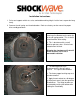
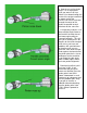
Installation Instructions 1. Raise and support vehicle at a safe, comfortable working height. Let the front suspension hang freely. 2. Remove the coil spring and shock absorber. Refer to a factory service manual for proper disassembly procedure. 3. For air spring clearance some trimming must be done on the outer lip of the coil spring pocket. This is what it should look like after cutting. 4. This is best done with a cut off wheel or plasma cutter. Grind all cuts smooth when finished.
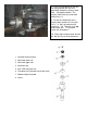
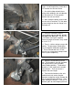
8. Place the Shockwave up into the coil spring pocket with the stud protruding through the factory shock hole. See diagram below. The factory shock hole may need to be drilled out to ¾”. 9. Fasten the Shockwave to the factory lower control arm using two 3/8” x 1 ¼” bolt, flat washers and nylok nuts. The T-bar will sit on top of the lower arm. (This picture shows the StrongArms) 10. Ride height will be around 90-100 psi, but will vary to driver preference. 1. Stud top aluminum base 2.
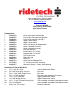
350 S. St. Charles St. Jasper, In. 47546 Ph. 812.482.2932 Fax 812.634.6632 www.ridetech.com Part # 11027199 55-57 Chevy Rear AirBar (One Piece Frame) Components: 1 90000160 1 90000558 1 90000556 1 90000554 1 90000555 4 90000552 1 90000550 1 90000551 8 90001942 4 90000956 1 90000941 2 90001617 1 90000266 4 90001584 2 90001589 6 99752004 4 90002067 Driver side lower axle bracket Passenger side lower axle bracket Front cross member (33.
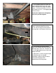
1. Raise the vehicle to a safe and comfortable working height. Use jack stands to support the vehicle with the suspension hanging freely. 2. Support the axle and remove the leaf springs, shocks, bump stops, pinion snubber and tail pipes. Refer to the factory service manual for proper disassemble procedures. 3. The parking brake brackets will be in the way of the 4 link and must be removed. Loosen the parking brake adjustment nut and remove the cable from the frame bracket.
5. Use a couple clamps to secure the crossmember between the frame rails. Slide it forward to the edge of the body mounts. Drill the holes with a 5/16” bit and thread the 3/8” x 1” self-tapping bolts in one at a time. Do not over tighten the self-tapping bolts; they can be stripped. 6. The location of the upper Shockwave mount is determined by measuring 20 1/4” from the edge of the bracket to the large hole in the bottom of the frame. 7.
. How do you set the pinion angle? On a single-piece shaft you want to set it up where a line drawn through the center of the engine crankshaft or output shaft of the transmission and a line drawn through the center of the pinion are parallel to each other but not the same line. A simple way to do this is to place a digital angle finder or dial level on the front face of the lower engine pulley or harmonic balancer.
. Pinion angle must be set at ride height. At ride height there should be 4 1/2” between the axle and frame. 11. One trick to help maintain these setting while welding in the axle bracket is to tack weld a 4 1/2” long spacer between the axle and frame. 12. After setting the pinion angle, make sure the axle is centered. This can done by measuring from the axle flange in to the frame rail. 13. Install the 4 link bars into the crossmember and axle bracket, but do not tighten the bolts yet.
17. Bolt the lower Shockwave mount to the axle bracket using the 5/8” x 3/4” Allen bolt. Apply anti-seize to the threads. It is easier to remove the bars to install these bolts. 18. There is a driver and passenger side bracket, the correct bracket will offset the Shockwave toward the wheel. 19. Bolt the diagonal link into place with a spacer on both sides of it using a 5/8” x 2 3/4” bolt and nyloc. It should measure 30 1/4" C-C. 20. Install the parking brake cable into the new tab on the cross member. 21.
25. Remove the spacer from between the axle and frame. 26. A new brake line tab is supplied and will mount just below the original. Make sure it clears the bar through full suspension travel. 27. Driving height will be with approximately 13" from center eye to center eye.
350 S. St. Charles St. Jasper, In. 47546 Ph. 812.482.2932 Fax 812.634.6632 www.ridetech.com Part # 24040701 7000 Series Shockwaves RQ Series - 4” Diameter - 5” Stroke - .625” Bearing/.625” Bearing 2 24049999 4.1” Stroke RQ Series Shock 2 24090799 7000 series Shockwave bellow assembly 2 90002021 Non-Adjustable Short eye mount (1.7” tall) 4 90001994 .625” I.D.
7000 Series Shockwave Use these spacers when mounting on 5/8” bolt. Compressed Height Ride Height Extended Height 4” Inflated Diameter Use these spacers when mounting on 1/2” bolt. 10.6” 13” 14.
350 S. St. Charles St. Jasper, In. 47546 Ph. 812.482.2932 Fax 812.634.6632 www.ridetech.
350 S. St. Charles St. Jasper, In. 47546 Ph. 812.482.2932 Fax 812.634.6632 www.ridetech.com ARC4000 Compressor System Instructions These are some general guidelines to follow when installing your new RidePro air control system. Depending on the vehicle there are many different ways to plumb the system. Start out by planning a lay out of where you want everything to be mounted.
Mounting the RidePro Air Valves The valves, like the compressor, are sealed and can be mounted in the same locations. Although if the vehicle will be exposed to freezing temperatures it is a good idea to mount them in the engine bay if possible to reduce the possibility of freezing. They can be mounted in any position. Mount the valves higher than the tank to avoid moisture build up. This could cause the air pressure sensors to give a faulty reading.
ARC4000 Wiring at control panel: Gray connects to gauge light Red connects to “key on” power at fuse box
Relay Wiring Diagram