
Full Product Manual


designed for use with pipe.
See “Setting The Groove
Diameter For Copper Tube” for use with copper tube.
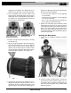
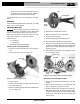
3. Turn the adjusting screw clockwise until the head
touches the step of the depth gauge. Turn the groove
depth gauge to the grooving position
(Figure 10B).
If
the gauge is not in the grooving position it will prevent
grooving and may be damaged.
4. Prepare a test groove
(follow the steps for “Forming
the Roll Groove).
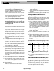
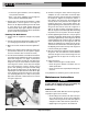
5. Measure the groove diameter. The best method for
measuring groove diameter is the use of a diameter
tape
(see Accessories Section)
. Snugly wrap the
diameter tape around the pipe in the groove. Make
sure that the tape sits flat in the bottom of the groove,
and read the groove diameter.
(See Figure 11.)
Figure 11 – Checking Groove Diameter With A Diameter
Tape
6. Compare the measured groove diameter to the re -
quired groove diameter as shown in
Table I or III
or as
specified by the groove fitting manufacturer. If the
measured groove is outside of the required groove
Ridge Tool Company 11
975 Combo Roll Groover
diameter, the adjusting screw must be repositioned to
give the correct groove diameter.
• To increase groove diameter, turn the adjusting
screw clockwise.
• To decrease groove diameter, turn the adjusting
screw counter-clockwise.
• Each
1
/
4
turn of the adjusting screw changes the
groove diameter approximately 0.02".
7. Repeat steps 4-6 until the groove diameter is within
specifications. If the groove is too large, the groover
can be adjusted and the groove made smaller. If the
groove is too small, another groove will need to be
made. Proper groove diameter is important to insure
connection performance. Out of specification grooves
could cause joint failure.
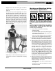
Forming The Roll Groove
1. Confirm that the equipment and pipe are properly
set up.
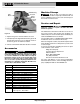
Figure 12 – Roll Groover Operating Position
2. Assume a proper operating position. Position the
power drive foot switch so that the operator can con-
trol the power drive, the roll groover and the pipe to be
grooved. As shown in
Figure 12
, the position should
allow the operator to:
Figure 10B – Gauge In
Grooving Position
Figure 10A – Place Correct
Step of Gauge Under
Adjusting Screw Head