OSCILLATING EDGE BELT/SPINDLE SANDER
Table of Contents Section Page Supporting Oscillating Edge Belt/ Spindle Sander to Sawhorses ......... 17 Alignment ........................................... 17 Squaring Front Table ........................ 17 Aligning Belt To Miter Gauge Slot ..... 18 Removing/Installing the Sanding Belt 19 Tensioning and Tracking ................... 19 Getting to Know Your Spindle Sander ............................................ 20 On-Off Switch ....................................
Safety Instructions For Oscillating Edge Belt/ Spindle Sander WARNING: means if the safety information is not followed someone could be seriously injured or killed. CAUTION: means if the safety information is not followed someone may be injured. Safety is a combination of common sense, staying alert and knowing how your oscillating edge belt/spindle sander works. Read this manual to understand this sander.
Safety Instructions for Oscillating Edge Belt/ Spindle Sander (continued) Read the following WARNING labels found on the sander: When Installing Or Moving The Sander cause electrocution, serious injury or worse. To reduce the risk of injury from unexpected sander movement: • Always unplug the sander before moving it. • Put the sander on a firm level surface where there is plenty of room for handling and properly supporting the workpiece. • Attach rubber feet. • Support the sander so it does not rock.
Before Each Use Disconnect the sander to reduce the risk of injury from accidental starting. Turn switch off, unplug sander and remove the switch key before changing the setup or sanding drum. Inspect your sander. Check for: • alignment of moving parts, • binding of moving parts, • broken or damaged parts, • work parts that cause a gap larger than 1/16" between work support and sanding surface, • sanding belt narrower than 4 inches.
Safety Instructions for Oscillating Edge Belt/ Spindle Sander (continued) of THROWBACKS - when the workpiece catches the sanding drum and is torn from your hands: • Make sure there is no debris between the workpiece and its supports. • When sanding irregularly shaped workpieces, plan your work support so it will not slip and be pulled from your hands. • Use extra caution with large, very small or awkward workpieces. • Never use this tool to finish pieces too small to hold by hand.
tors a safe distance from the sander and workpiece. Don’t force tool. It will perform better and safer at its designed rate. Press workpiece against the sanding sleeve hard enough to begin sanding without bogging down or binding spindle or belt. Before freeing any jammed material: • Turn switch “OFF”. • Unplug the sander. • Wait for all moving parts to stop. When Sander is Running Before starting your work, watch the sander while it runs.
Precautions To Take When Sanding Paint (continued) project. If project lasts for an extended period of time, clean work area often. Items such as sanding dust, vacuum filter bags, plastic drop cloths, etc. should be placed in a sealed container and disposed of properly. Clean all items exposed to sanding dust. 4. Protect the environment when sanding paint. Use a dust collection system if possible. Seal the work area with plastic if necessary. Do not track paint dust outside the work area. 5.
If the grounding instructions are not completely understood, or if you are in doubt as to whether the tool is properly grounded, check with a qualified electrician or service personnel. 110-120 Volt, 60 Hz. Tool Information NOTE: The plug supplied on your tool may not fit into the outlet you are planning to use. Your local electrical code may require slightly different power cord plug connections.
Motor Specifications and Electrical Requirements (continued) Motor Safety Protection IMPORTANT: To reduce the risk of motor damage, the motor should be blown out or vacuumed frequently to keep sawdust from interfering with normal motor ventilation. 1. Connect this tool to a power source with the appropriate voltage for your model and a 15-amp branch circuit with a 15-amp fuse or circuit breaker. Using the wrong size fuse can damage the motor. 2.
Unpacking and Checking Contents 1. Remove tool from carton by lifting unit. 2. Place the tool on a secure, stationary work surface and look the tool over carefully. WARNING: For your own safety, never connect plug to power source outlet, or insert switch key until all assembly steps are complete and until you have read and understood the entire owners manual.
Assembly NOTE: The sander is preassembled except for the attachment of the rubber feet. Mounting Rubber Feet To Base Place the sander directly on the table surface. 1. From the parts bag locate the four rubber feet. 2. Place the sander on its side so the bottom of the base is facing toward the front. 3. Locate the four holes in each corner of the base and place one of the rubber feet in each of these holes. 4.
Removing the Sanding Belt Assembly Spindle Knob WARNING: To reduce the risk of injury from accidental start, make sure tool is unplugged before removing the sanding belt assembly. Backstop Knob 1. Loosen the backstop knob and pivot the backstop out of the way. Tighten the backstop knob. 2. Remove the spindle knob and lift off the sanding belt assembly. NOTE: Knob turns clockwise to loosen. 3. Store assembly in pocket in rear of base. Installing the Sanding Belt Assembly Wear Plate 1.
Assembly (continued) Installing Sanding Sleeves Larger than 1/2" Diameter WARNING: To reduce the risk of injury from accidental starting, always turn switch “OFF” and remove switch key before removing or replacing the spacer ring inserts, sleeves and drums. Straightedge 1. Remove the fan and clean sawdust from inside table recess. 2. Slide the fan onto the motor shaft (vanes face down) aligning slot with roll pin. The fan is used with all drums and sleeves. 3. Install the table insert. 4.
Installing Sanding Sleeves for the 1/2" Diameter Sanding Drum ring insert in the table recess. 6. Locate 1/2" sanding sleeve and slide it on the spindle. (Rubber drum is not used.) 7. Install the upper spindle washer and tighten the knob. Do not overtighten. NOTE: Knob turns counterclockwise to tighten. 8. Plug the power cord in the power source and install the yellow switch key.
Assembly (continued) Bolting Oscillating Edge Belt/ Spindle Sander To Workbench If sander is to be used in a permanent location, it should be fastened securely to a firm supporting surface such as a workbench, with either bolts or drywall screws. Fastening with bolts 1. Use 1/4" bolts, washers, and nuts (not included). The bolt length should be 1-1/2" plus the thickness of the workbench. 2. Locate and mark the holes where the sander is to be mounted. 3. Drill (4) 3/8" diameter holes through workbench. 4.
Supporting Oscillating Edge Belt/ Spindle Sander to Sawhorses The sander has provisions for being supported by sawhorses. The sawhorse can be built with the crosspiece either vertical or horizontal. Make sure the sawhorses are secure. Alignment Squaring Front Table WARNING: To reduce the risk of injury from accidental start, make sure tool is unplugged before aligning. Combination Square Combination Square Must be True Draw Light Line on Board Along This Edge Tools Needed Straight Edge of Board 1.
Alignment (continued) Aligning Belt To Miter Gauge Slot Adjust Bed Assembly Parallel to Miter Gauge Slot The sanding belt is installed at the factory; however, check and make sure the belt is parallel to the miter gauge groove: 1. Use a combination square to check the distance from the miter gauge groove to the belt assembly as shown. 2. If adjustment is required, use a 5/32 inch hex “L” wrench provided with unit to loosen the two flat head socket recess screws on the table. 3.
Removing/Installing the Sanding Belt Tensioning and Tracking Tensioning Lever WARNING: To reduce the risk of injury from accidental start, make sure tool is unplugged before removing or installing sanding belt. Belt Tracking Some sanding belts have a “directional arrow” on the inside or smooth side. If there is an arrow, the belt must run in the direction of the arrow so the splice will not come apart. If there is no arrow the belt may be put on either direction. 1.
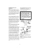
Getting to Know Your Spindle Sander 3 Tracking Knob 2 Belt Tension Lever 4 Spindle Knob 1 Sanding Belt 5 Backstop Table Adjustment Screws (Left and Right Side) 9 Front Table Lock Knob 6 Front Table Detent 8 Sanding Drum(s)/ 15 Table Insert 7 Spacer Rings 10 On-Off Switch Sleeves(s) Slots for “Saw Horse” Mounting 11 Backstop Knob 12 Dust Collection Port 14 3/32 Hex “L” Wrench 5/32 Hex “L” Wrench 13 Table Insert/ Sanding Belt Storage WARNING: To reduce the risk of injury from accidental start, turn
10. On-Off Switch 11. Backstop Knob. Loosening knob allows backstop to be pivoted. 12. Dust Collection Port. 2-1/2" opening for wet/dry vac hook-up. 13. Table Insert/Sanding Belt Storage. Holds table insert or sanding belt when not being used. 14. Hex “L” Wrench. Use 3/32" wrench to adjust front table and table insert. Use 5/32" wrench to adjust belt to miter gauge slot. 15. Table Insert. Helps to support workpiece when drum sanding.
Safety Instructions for Oscillating Edge Belt/Spindle Sander Before Using The Sander WARNING: To reduce the risk of mistakes that could cause serious, permanent injury, do not plug the sander in until the following steps are completed. • Assembly. (See pages 12-19) • Learn the use and function of the ON-OFF switch. (See page 21) • Review and understanding of all safety instructions and operating procedures in this manual. • Review of the maintenance methods for this sander.
If any part is missing, bent, or broken in any way, or any electrical parts don’t work properly, turn the sander off and unplug the sander. Replace damaged, missing, or failed parts before using the sander again. Disconnect the sander to reduce the risk of injury from accidental starting. Turn switch off, unplug sander and remove the switch key before changing the setup or sanding drum. Maintain tools with care. Keep the sander clean for maximum and safest performance.
Safety Instructions for Oscillating Edge Belt/ Spindle Sander (continued) too small to hold by hand. • Use extra supports (tables, saw horses, blocks, etc.) for any workpieces large enough to tip when not secured to the work surface. • Never use another person as a substitute for a table extension, or as additional support for a workpiece that is longer or wider that the basic sander table, or to help feed, support or pull the workpiece. • Sand only one workpiece at a time.
Before freeing any jammed material: • Turn switch “OFF”. • Unplug the sander. • Wait for all moving parts to stop. Before Leaving The Sander Turn switch off. Don’t leave tool until the unit comes to a complete stop. Make workshop child-proof. Remove the yellow switch key. Store it away from children and others not qualified to use the tool. Disconnect master switches. Lock the shop. Precautions To Take When Sanding Metals When sanding metals, sparks or hot fragments could cause a fire.
Basic Sanding Operation NOTE: Do Not use sander without sandpaper. Doing so will damage the rubber drum. Select and install the desired sanding sleeve for your particular application. Sanding sleeves from 1/2" to 2" can be used with this sander. Choose one that is close in size to the workpiece you are sanding. Also install the appropriate spacer ring insert (page 15).
Surface Sanding on the Sanding Belt WARNING: To reduce the risk of injury from slips, jams or thrown pieces, adjust the backstop to clear the sanding surface by no more than 1/16 of an inch. When checking clearance between the sanding belt and backstop, press the sanding belt flat against the metal bed beneath it. Hold the workpiece firmly with both hands, keeping fingers away from the sanding belt. Keep the end butted against the backstop and move the work evenly across the sanding belt.
Basic Sanding Operation (continued) Feed Direction WARNING: To prevent thrown workpiece, feed workpiece against sanding sleeve from left to right as shown. The sanding sleeve rotates clockwise. Feed the workpiece against the sanding sleeve from left to right as shown. When fed from left to right, the rotation of the sanding sleeve sands against the workpiece.
Maintenance WARNING: For your own safety, turn switch “OFF” and remove plug from power source outlet before adjusting or maintaining your sander. WARNING: To reduce the risk of electrocution or fire, any repairs to electrical systems should be done only by qualified service technicians. Unit must be reassembled exactly to factory specifications. If power cord is worn or cut, or damaged in anyway, have it replaced immediately. Frequently blow out or vacuum out any dust that may accumulate inside the motor.
Troubleshooting WARNING: For your own safety, turn switch “OFF”, and remove plug from power source outlet before troubleshooting your sander. TROUBLE PROBABLE CAUSE REMEDY 1. Motor gearbox not oper- 1. Consult Authorized Service Excessive noise ating correctly. Center, any attempt to repair NOTE: The sander will this motor or gearbox may make some noise when create a hazard unless it is operating normally repair is done by a qualified service technician. 1.
TROUBLE PROBABLE CAUSE REMEDY Frequent opening of fuse or circuits breaker 1. Feed work slower 1. Motor overloaded. 2. Incorrect fuses or circuit 2. Install correct fuse or circuit breakers. breaker in power line. 3. Have relay replaced. Con3. Relay not operating. sult Authorized Service Center. Any attempt to repair this relay may create a hazard unless repair is done by a qualified service technician. Motor will not run 1. Damaged On-Off Switch/Cord. 2.
Repair Parts Parts List For RIDGID Oscillating Edge Belt/Spindle Sander Model EB44241 RIDGID parts are available on-line at www.ridgidparts.
Repair Parts Parts List For RIDGID Oscillating Edge Belt/Spindle Sander Model EB44241 RIDGID parts are available on-line at www.ridgidparts.com Figure 1 Always order by Part Number—Not by Key Number Key No. 1 2 3 4 5 6 7 8 9 10 11 12 13 14 15 16 17 18 19 20 21 22 23 24 25 Part No. Key No. Description Knob, Spindle Washer 21/64 x 5/8 x 1/32 Drum, Sanding 3/4" 822304 See pg. 29 †Drum, Sandpaper Plate, Throat 2" 825808 See pg.
Repair Parts Parts List For RIDGID Oscillating Edge Belt/ Spindle Sander Model EB44241 RIDGID parts are available on-line at www.ridgidparts.com Figure 2 9 19 4 5 18 4 6 7 1 3 4 10 16 2 17 19 8 2 15 12 11 13 8 14 Always order by Part Number—Not by Key Number Key No. Part No. Key No. Description Knob 10-32 x 1-1/4 825539 Washer 12 mm 1.0. 830306 Drum/Drive Asm.
Notes 35
RIDGID® HAND HELD AND STATIONARY POWER TOOL LIMITED THREE YEAR WARRANTY AND 90 DAY SATISFACTION GUARANTEE POLICY This product is manufactured under license from Ridgid, Inc. by One World Technologies, Inc.. All warranty communications should be directed to One World Technologies, Inc. at (toll free) 1-866-539-1710.