
Manual

micro CA-300 Inspection Camera
14
The copy and delete options are available
from computer operation.
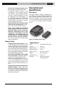
Connecting to TV
The micro CA‑300 Inspection Camera can be
connected to a television or other monitor
for remote viewing or recording through the
included RCA cable.
Open the right side port cover (Figure 3). In‑
sert the RCA cable into the TV‑Out jack. Insert
the other end of the cable into the Video‑In
jack on the television or monitor. Check to
make sure the video format (NTSC or PAL)
output is set properly. The television or
monitor may need to be set to the proper
input to allow viewing.
Using with SeeSnake
®
Inspection
Equipment
The micro CA‑300 Inspection Camera can
also be used with various SeeSnake Inspec‑
tion Equipment and is specically designed
to be used with the microReel, microDrain™
and the nanoReel Inspection Systems. When
used with these types of equipment, it retains
all of the functionality described in this man‑
ual. The micro CA‑300 Inspection Camera can
also be used with other SeeSnake Inspection
Equipment for viewing and recording only.
For use with SeeSnake Inspection Equip‑
ment, the imager head and any cable exten‑
sions must be removed. For the microReel,
microDrain, nanoReel and similar equip‑
ment, see the operator’s manual for informa‑
tion on proper connection and use. For other
SeeSnake Inspection Equipment (typically a
reel and monitor), an adapter must be used
to connect the micro CA‑300 Inspection
Camer a to a Video‑Out port on the SeeSnake
Inspec tion Equipment. When connected in
this manner, the micro CA‑300 Inspection
Camera will display the camera view and can
be used for recording.
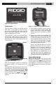
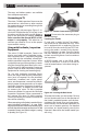
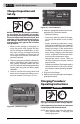
When connecting to SeeSnake Inspection Equip‑
ment (microReel, microDrain™, or nano ‑Reel),
align the interconnect module connected to your
reel with the cable connector onthe micro CA‑300
Inspection Camera, and slide it straight in, seating
it squarely. (See Figure 19.)
Figure 19 - Camera Connector Plug Installed
NO TICE
Do not twist the connector plug to
prevent damage.
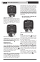
Locating the Sonde
If used with a sonde (In‑Line Transmitter),
the sonde can be controlled two ways. If the
reel is equipped with a sonde key, that can
be used to turn the sonde ON and OFF. Oth‑
erwise, the sonde is turned ON by decreas‑
ing LED brightness to zero. Once the Sonde
has been located, the LEDs can be returned
to their normal brightness level to continue
the inspection.
A RIDGID locator such as the SR‑20, SR‑60,
Scout, or NaviTrack® II set to 512 Hz can be
used to locate features in the drain being in‑
spected.
Figure 20 - Locating the Reel Sonde
To locate the Sonde, turn the locator ON and
set it to Sonde mode. Scan in the direction of
the Sonde’s probable location until the loca‑
tor detects the Sonde. Once you have detect‑
ed the Sonde, use the locator indications to
zero in on its location precisely. For detailed
instructions on Sonde locating, consult the
Oper ator’s Manual for the locator model you
are using.