OPERATOR'S MANUAL 10 in. (254 mm) COMPOUND MITER SAW WITH EXACTLINE™ LASER MS1065LZ - Double Insulated Your miter saw has been engineered and manufactured to our high standards for dependability, ease of operation, and operator safety. When properly cared for, it will give you years of rugged, trouble-free performance. WARNING: To reduce the risk of injury, the user must read and understand the operator’s manual before using this product. Thank you for buying a Ridgid product.
TABLE OF CONTENTS Introduction ...................................................................................................................................................................... 2 Symbols ............................................................................................................................................................................ 3 Rules for Safe Operation ..................................................................................................
RULES FOR SAFE OPERATION The purpose of safety symbols is to attract your attention to possible dangers. The safety symbols, and the explanations with them, deserve your careful attention and understanding. The safety warnings do not by themselves eliminate any danger. The instructions or warnings they give are not substitutes for proper accident prevention measures. SYMBOL MEANING DANGER: Indicates an imminently hazardous situation, which, if not avoided, will result in death or serious injury.
RULES FOR SAFE OPERATION USE THE RIGHT TOOL FOR THE JOB. Do not force the tool or attachment to do a job it was not designed for. Use it only the way it was intended. perform its intended function. Check for alignment of moving parts, binding of moving parts, breakage of parts, mounting and any other conditions that may affect its operation. A guard or other part that is damaged must be properly repaired or replaced by an authorized service center to avoid risk of personal injury.
RULES FOR SAFE OPERATION BE SURE BLADE PATH IS FREE OF NAILS. Inspect for and remove all nails from lumber before cutting. clear and allow the saw blade to come to a complete stop. Disconnect your saw from the power supply and securely retighten the blade bolt. NEVER TOUCH BLADE or other moving parts during use for any reason. REPLACEMENT PARTS. All repairs, whether electrical or mechanical, should be made at your nearest authorized service center. BE SURE THE BLADE CLEARS THE WORKPIECE.
RULES FOR SAFE OPERATION THIS TOOL shall have the following markings: a) Wear eye protection. b) Keep hands out of path of saw blade. c) Do not operate saw without guards in place. d) Do not perform any operation freehand. e) Never reach around saw blade. f) Turn off tool and wait for saw blade to stop before moving workpiece or changing settings. g) Disconnect power (or unplug tool as applicable) before changing blade or servicing. h) No load speed. ALWAYS carry the saw only by the carrying handle.
SPECIFICATIONS Blade Arbor .................................................................................................................................................... 5/8 in. (16 mm) Blade Diameter ............................................................................................................................................. 10 in. (254 mm) Input .........................................................................................................................
UNPACKING Examine all parts to make sure no breakage or damage has occurred during shipping. If any parts are damaged or missing, please call 1-866-539-1710 for assistance. Your Compound Miter Saw has been shipped completely assembled except for the blade, miter lock handle, dust guide or dust bag, laser guide, and work clamp. Remove all loose parts from the carton. Separate and check with the list of loose parts. See Figure 1. Remove the packing materials from around your saw.
LOOSE PARTS LIST The following items are included with your Compound Miter Saw: 10 in. (254 mm) Saw Blade Socket Head Screw (2) Miter Lock Handle Washer (2) Dust Bag Blade Wrench Dust Guide Exactline™ Laser Work Clamp Hex Bolt 6 mm Hex Key Operator's Manual 8 mm Hex Key Warranty Registration Card Table Extension LASER DUST GUIDE SAW BLADE HEX BOLT SOCKET HEAD SCREWS WASHER TABLE EXTENTION DUST BAG 8 mm HEX KEY WORK CLAMP BLADE WRENCH 6 mm HEX KEY MITER LOCK HANDLE Fig.
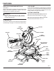
FEATURES KNOW YOUR COMPOUND MITER SAW 10 IN. BLADE See Figure 2. Before using this product, familiarize yourself with all operating features and safety requirements. However, do not let familiarity with the tool make you careless. A 10 in. (254 mm) saw blade is included with your compound miter saw. It is fine for most wood cutting operations, but for fine joinery cuts or cutting plastic, use one of the accessory blades available from your nearest dealer.
FEATURES BLADE WRENCH / STORAGE AREA See Figure 2. A blade wrench is packed with your saw. One end of the wrench is a phillips screwdriver and the other end is a 5 mm hex key. Use the hex key end when installing or removing blade and the phillips end when removing or loosening screws. A storage area for the blade wrench is located behind the fence. SPINDLE LOCK BUTTON CARRYING HANDLE See Figure 3.
FEATURES POSITIVE STOPS ON MITER TABLE MOUNTING HOLES Positive stops have been provided at 0°, 11.25°,15°, 22.5°, 31.62°,and 45°. The 0°, 11.25°,15°, 22.5°, 31.62°,and 45° positive stops have been provided on both the left and right side of the miter table. See Figure 6. Your compound miter saw should be mounted to a firm supporting surface such as a workbench. Four bolt holes have been provided in the saw base for this purpose. Each of the four mounting holes should be bolted securely using 3/8 in.
ASSEMBLY WARNING: To prevent accidental starting that could cause possible serious personal injury, assemble all parts, make sure all adjustments are complete, and make sure all fasteners are secure before connecting saw to power supply. Saw should never be connected to power supply when you are assembling parts, making adjustments, installing or removing blades, or when not in use. TO LOOSEN TO CONTROL TIGHTEN ARM MITER LOCK HANDLE See Figure 7.
ASSEMBLY TABLE EXTENSION TABLE EXTENSION See Figure 11. The table extension can be used on the left side of your miter saw. To assemble and install the table extension: Insert socket head screw and washer into the two holes in the side of the miter saw base. Tighten securely. TO INSTALL BLADE See Figure 12. WARNING: A 10 in. (254 mm) blade is the maximum blade capacity of your saw. Never use a blade that is too thick to allow outer blade washer to engage with the flats on the spindle.
ASSEMBLY Fit saw blade inside lower blade guard and onto spindle. The blade teeth point downward at the front of saw as shown in figure 12. WARNING: Make sure the spindle lock button is not engaged before reconnecting saw into power source. Never engage spindle lock button when blade is rotating. Replace outer blade washer. The double "D" flats on the blade washers align with the flats on the spindle. Depress spindle lock button and replace blade bolt.
ADJUSTMENTS The edge of the square and the saw blade should be parallel as shown in figure 14. If the front or back edge of the saw blade angles away from the square as shown in figures 15 and 16, adjustments are needed. Loosen the socket head screws that secure the miter fence to the miter table. See Figure 13. Rotate the miter fence left or right until the saw blade is parallel with the square. Retighten the screws securely and recheck the blade-tofence alignment.
ADJUSTMENTS BEVEL LOCK KNOB SQUARING THE BLADE TO THE MITER TABLE See Figures 18 - 20. Unplug your saw. MITER FENCE WARNING: Failure to unplug your saw could result in accidental starting causing possible serious personal injury. BLADE Pull the saw arm all the way down and engage the lock pin to hold the saw arm in transport position. Loosen the miter lock handle approximately one-half turn.
ADJUSTMENTS PIVOT ADJUSTMENTS Note: These adjustments were made at the factory and normally do not require readjustment. TRAVEL PIVOT ADJUSTMENT DEPTH STOP ADJUSTMENT SCREW The saw arm should rise completely to the up position by itself. If the saw arm does not raise by itself or if there is play in the pivot joints, have saw repaired by at your nearest AUTHORIZED SERVICE CENTER.
OPERATION CUTTING WITH MITER SAW YOUR Align cutting line on the workpiece with the edge of saw blade. Grasp the stock firmly with one hand and secure it against the fence. Use the optional work clamp or a C-clamp to secure the workpiece when possible. See Figure 22. Before turning on the saw, perform a dry run of the cutting operation just to make sure that no problems will occur when the cut is made. Grasp the saw handle firmly then squeeze the switch trigger.
OPERATION SCALE AT 48º BEVEL CUT See Figures 23 - 25. A bevel cut is made by cutting across the grain of the workpiece with the blade angled to the workpiece. A straight bevel cut is made with the miter table set at the zero degree position and the blade set at an angle between 0° and 48°. Note: It may be necessary to adjust the sliding miter fence to assure proper clearance prior to making the cut. Pull out the lock pin and lift saw arm to its full height. Loosen the miter lock handle.
OPERATION Grasp the stock firmly with one hand and secure it against the fence. Use the optional work clamp or a C-clamp to secure the workpiece when possible. See Figure 24. WARNING: To avoid serious personal injury, always keep your hands outside the no hands zone; at least 3 in. (7.6 cm) from blade. Never perform any cutting operation freehand (without holding workpiece against the fence). The blade could grab the workpiece if it slips or twists.
OPERATION Align the cutting line on the workpiece with the edge of saw blade. Grasp the stock firmly with one hand and secure it against the fence. Use the optional work clamp or a C-clamp to secure the workpiece when possible. See Figure 26. WARNING: To avoid serious personal injury, always keep your hands outside the no hands zone; at least 3 in. (7.6 cm) from blade. Never perform any cutting operation freehand (without holding workpiece against the fence).
OPERATION CUTTING COMPOUND MITERS To aid in making the correct settings, the compound angle setting chart below has been provided. Since compound cuts are the most difficult to accurately obtain, trial cuts should be made in scrap material, and much thought and planning made, prior to making your required cut. PITCH OF SIDE 0° 5° 10° 15° 20° 25° 30° 35° NUMBER OF SIDES 4 5 6 M- 45.00° M- 36.00° M- 30.00° B- 0.00° B- 0.00° B- 0.00° M- 44.89° M- 35.90° M- 29.91° B- 3.53° B- 2.94° B- 2.50° M- 44.
OPERATION CUTTING CROWN MOLDING Your compound miter saw does an excellent job of cutting crown molding. In general, compound miter saws do a better job of cutting crown molding than any other tool made. In order to fit properly, crown molding must be compound mitered with extreme accuracy. The two contact surfaces on a piece of crown molding that fit flat against the ceiling and the wall of a room are at angles that, when added together, equal exactly 90°.
OPERATION Bevel Angle Setting Type of Cut 33.85° Left side, inside corner 1. Top edge of molding against fence 2. Miter table set right 31.62° 3. Save left end of cut 33.85° Right side, inside corner 1. Bottom edge of molding against fence 2. Miter table set left 31.62° 3. Save left end of cut 33.85° Left side, outside corner 1. Bottom edge of molding against fence 2. Miter table set left 31.62° 3. Save right end of cut ° 33.85 WRONG Right side, outside corner 1.
LASER GUIDE Make several practice cuts on different styles and thickness of material. Follow the directions below for using your Laser Guide. Removing Your Mark: Position the laser line near the left edge of your mark on the work surface in order to remove the mark. To Cut Your Mark: Position the laser line near or over your mark on the work surface in order to cut the mark. To Leave Your Mark: Position the laser line near the right edge of your mark on the work surface in order to leave the mark.
LASER GUIDE CHANGING THE BATTERIES SCREWS See Figure 35. Unplug your saw. WARNING: Failure to unplug your saw could result in accidental starting causing possible serious personal injury. Remove the laser guide from the saw. Lay laser guide on a flat surface with the two phillips screws facing upward. Remove the screws and separate the laser guide cover from the laser guide support. Remove the three button cell batteries using a non-conductive device such as a toothpick.
MAINTENANCE WARNING: CAUTION: When servicing, use only identical replacement parts. Use of any other part may create a hazard or cause product damage. Check extension cords before each use. If damaged, replace immediately. Never use tool with a damaged cord since touching the damaged area could cause electrical shock resulting in serious injury. GENERAL Avoid using solvents when cleaning plastic parts.
WARRANTY RIDGID® HAND HELD AND STATIONARY POWER TOOL LIMITED THREE YEAR WARRANTY AND 90-DAY SATISFACTION GUARANTEE POLICY This product is manufactured by One World Technologies, Inc., under a trademark license from Ridgid, Inc. All warranty communications should be directed to One World Technologies, Inc., attn: RIDGID handheld and stationary power tool technical service at (toll free) 1-866-539-1710.
OPERATOR'S MANUAL 10 in. (254 mm) COMPOUND MITER SAW WITH EXACTLINE™ LASER MS1065LZ - Double Insulated CUSTOMER SERVICE INFORMATION For parts or service, contact your nearest Ridgid authorized service center. Be sure to provide all relevant information when you call or visit. For the location of the authorized service center nearest you, please call 1-866-539-1710 or visit us online at www.ridgid.com. The model number of this tool is found on a plate attached to the motor housing.