
- Ridgid 12 In. Compound Miter Saw Operator's Manual

19
1
5
2
0
2
5
3
0
3
5
4
0
4
5
5
0
1
0
ASSEMBLY
CUTTING A SLOT IN THE ZERO CLEARANCE
THROAT PLATE
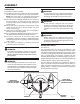
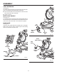
In order to use your compound miter saw, you must cut
a slot through the zero clearance throat plate to allow for
blade clearance. To cut the slot, set your saw at 0
°
miter,
turn saw on and allow the blade to reach full speed, then
carefully make a straight cut as far as it will go through the
throat plate. Turn your saw off and allow the blade to come
to a complete stop before raising the saw arm.
Next, adjust the bevel angle to 45
°
, turn your saw on and al-
low the blade to reach full speed, then carefully make another
cut through the zero clearance throat plate. The slot in the
throat plate will then be wide enough to allow the blade to
pass through it at any angle from 0
°
to 45
°
.
NOTE: Many of the illustrations in this manual show only
portions of the compound miter saw. This is intentional
so that we can clearly show points being made in the
illustrations. Never operate the saw without all guards se-
curely in place and in good operating condition.
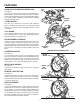
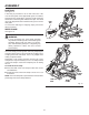
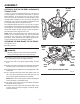
SQUARING THE SAW BLADE TO THE FENCE
See Figures 16 - 21
Unplug the saw.
WARNING:
Failure to unplug your saw could result in accidental
starting causing possible serious personal injury.
Pull the saw arm all the way down and engage the lock
pin to hold the saw arm in transport position.
Loosen the miter lock handle approximately one-half
turn.
Depress the miter lock plate and rotate the miter table
until the pointer on the control arm is positioned at 0
°
.
Release the miter lock plate and securely tighten the miter
lock handle.
Lay a framing square flat on the miter table. Place one
leg of the square against the fence. Slide the other leg
of the square against the flat part of saw blade.
NOTE: Make sure that the square contacts the flat part
of the saw blade, not the blade teeth.
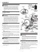
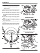
The edge of the square and the saw blade should be
parallel as shown in figure 17.
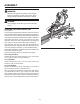
If the front or back edge of the saw blade angles away
from the square as shown in figures 19 and 20, adjust-
ments are needed.
Fig. 17
VIEW OF BLADE SQUARE WITH FENCE
Fig. 16
SLIDING
MITER
FENCE
BLADE
MITER
LOCK
PLATE
MITER
LOCK
HANDLE
FRAMING
SQUARE
MITER
TABLE
CAP HEAD
SCREWS