
- Ridgid 12 In. Compound Miter Saw Operator's Manual

20
1
5
2
0
2
5
3
0
3
5
4
0
4
5
5
0
1
0
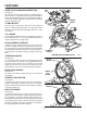
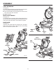
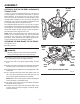
VIEW OF BLADE NOT SQUARE WITH FENCE,
ADJUSTMENTS ARE REQUIRED
Fig. 19
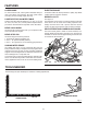
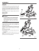
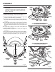
VIEW OF BLADE NOT SQUARE WITH FENCE,
ADJUSTMENTS ARE REQUIRED
Fig. 21
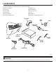
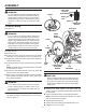
ASSEMBLY
INDICATOR
SCREW
SCALE
INDICATOR
MITER
SCALE
1
5
2
0
2
5
3
0
3
5
4
0
4
5
5
0
1
0
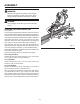
SLIDING
MITER
FENCE
MITER
TABLE
FRAMING
SQUARE
BLADE
SLIDING
MITER
FENCE
FRAMING
SQUARE
MITER
TABLE
BLADE
BEVEL
SCALE
INDICATOR
SCREW
SCALE
INDICATOR
INDICATOR
POINT
Fig. 20
CAUTION:
To keep from losing control of the unit, steady the
base with one hand while loosening the two bolts
with the other hand.
With the unit securely resting on a large stable surface,
tilt the unit by lifting up on one side of the base.
Using a combination wrench, loosen the two cap head
screws on the underside of the saw table.
Return the saw to its normal resting position. Make sure
the miter lock knob is loose but do not release the miter
lock plate.
Use the miter saw knob to move the table so that the
blade contacts the full length of the framing square. Turn
the miter lock knob clockwise to lock saw square to the
fence.
Tilt the unit by lifting up on one side of the base and
tighten cap head screws.
Recheck blade squareness to fence and readjust if
necessary.
Your saw has several scale indicators. After squaring adjust-
ments have been made, it may be necessary to loosen the
indicators screws and reset them to zero. See Figure 18.
Fig. 18