
User's Manual


Ridge Tool Company10
258/258XL Power Pipe Cutters
c. While holding onto cutter wheel assembly, pull
drive shaft out and lift cutter wheel assembly up
through top of pivot arm (Figure 12). If necessary,
lightly tap opposite end of square drive with ham-
mer or wrench to start removal.
NOTE! For multi-piece cutter wheel remove hub on cut-
ter wheel. Locate the three (3) allen screws with
lock washers and remove with
1
/
4
″ allen wrench
(supplied with cutter). Remove cover plate to
expose cutter wheel. Replace worn cutter wheel
with new wheel (Figure 12). Replace cover plate
and tighten allen screws with allen wrench.
d. Return cutter wheel assembly or new cutter wheel
to the cutter. Align square drive shaft with hub
assembly and insert until shoulder butts up against
inner race of bearing. Place washer and lock-nut
on reverse side of square drive. Tighten until lock-
nut bottoms out against washer.
NOTE! Do not over-tighten lock-nut. When nut bot-
toms out against washer, stop. Over-tightening
can reduce wheel’s ability to turn, requiring
more power from power drive, or it may cause
wheel to not track during cut.
2. Cutter wheel should easily and freely rotate in either
direction when lock-nut is properly tightened.
Transporting
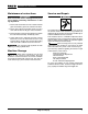
1. The 258 and 258XL are designed with hand-holds
located at top rear, and bottom of frame front, for
transporting the cutter (Figure 14). Do not use pivot
arm handle to transport, as it may cause damage to
the hydraulic cylinder.
2. Remove 700 Power Drive to reduce weight when
carrying.
WARNING
Two operators should carry the cutter when being
moved to prevent personal injury.
Transporting Using The Transport Cart
A two wheeled cart is available as an accessory to allow
for easier transporting. This transport cart, (see catalog for
ordering information), is compatible with the 258 (2
1
/
2
″ –
8″) as well as the 258XL (8″ – 12″). By using a “J” clamp
on the top frame handle along with a hitch pin through a
frame hole (Figure 14), the transport cart can easily be
installed.
NOTE! Transport cart does not interfere with the oper-
ation of the cutter and can remain attached.
Figure 14 – Hand-holds for Transporting
Transport Cart
Hole
Figure 12 – Remove Cutter Wheel Assembly
Figure 13 – Cutter Wheel Assembly