
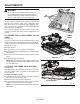
Replacement Part List

24 — English
OPERATION
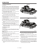
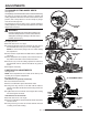
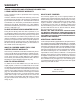
TO MAKE A BEVEL CUT
See Figure 33.
Bevel cuts are made by feeding the material into the cutting
wheel with the motor head at an angle. It is recommended
thatyouonlymakecutsat0˚and45˚angles.
WARNING:
Makingcutsatanglesotherthan0˚and45˚angles
could cause the cutting wheel to come in contact
with the sliding table resulting in damage to the
unit and/or possible serious injury.
Fillthewaterreservoirwithcleantapwater.
Using a straight edge or square, draw a line on the tile
with a marker or grease pencil.
Slide the saw table to the front of the water tray before
tilting the saw head.
Loosen the bevel knob.
Set the saw arm to a 45° angle and tighten the bevel
knob.
Turn the on/off switch to the ON position.
Let the cutting wheel build up to full speed and wait for
the wheel to get wet before moving the material into the
wheel.
Hold the material firmly against the sliding table fence
and feed the material into the cutting wheel.
When the cut is made, turn the saw OFF. Wait for the
cutting wheel to come to a complete stop before removing
any part of the material.
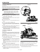
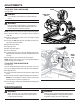
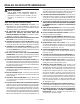
TO MAKE A PLUNGE CUT
See Figure 34.
Plunge cuts are made by positioning the material directly
underneath the cutting wheel and lowering the wheel onto
the workpiece. This allows pieces to be cut from the center
of the material.
Fillthewaterreservoirwithcleantapwater.
Using a straight edge or square, draw a line on the tile
with a marker or grease pencil.
Unlock the plunge lock lever on the motor head and raise
the motor head upward to its maximum height then lock
the plunge lock lever.
NOTE: The motor head is not spring loaded and will not
stay in the upright position with the plunge lock lever
unlocked.
Turn the on/off switch to the ON position.
Let the cutting wheel build up to full speed and wait for
the wheel to get wet before moving the material into the
wheel.
Holding the motor head firmly by the handle, unlock the
plunge lock lever and move the material into the desired
position for cutting.
Fig. 33
BEVEL
LOCK
KNOB
BEVEL CUT
PLUNGE CUT
Fig. 34
PLUNGE
LOCK LEVER
PLUNGE
LOCK LEVER
Slowly lower the motor head into the material to make
the cut.
Raise the motor head and lock the plunge lock lever.
Turn the on/off switch to the OFF position.
Slide the table away from the motor head then position
the work material for the next cut.