OPERATOR’S MANUAL 12 VOLT 1/4 in. IMPACT DRIVER RIGHT ANGLE R82233 Your impact driver has been engineered and manufactured to our high standards for dependability, ease of operation, and operator safety. When properly cared for, it will give you years of rugged, trouble-free performance. WARNING: To reduce the risk of injury, the user must read and understand the operator’s manual before using this product. Thank you for buying a RIDGID product.
TABLE OF CONTENTS n Introduction .....................................................................................................................................................................2 n General Safety Rules ................................................................................................................................................... 3-4 n Specific Safety Rules..................................................................................................................
GENERAL SAFETY RULES n Do not overreach. Keep proper footing and balance at all times. Proper footing and balance enable better control of the tool in unexpected situations. n Use safety equipment. Always wear eye protection. Dust mask, non-skid safety shoes, hard hat, or hearing protection must be used for appropriate conditions. n Do not wear loose clothing or jewelry. Contain long hair. Loose clothes, jewelry, or long hair can be drawn into air vents. n Do not use on a ladder or unstable support.
GENERAL SAFETY RULES SERVICE n When servicing a tool, use only identical replacement parts. Follow instructions in the Maintenance section of this manual. Use of unauthorized parts or failure to follow Maintenance Instructions may create a risk of shock or injury. n Tool service must be performed only by qualified repair personnel. Service or maintenance performed by unqualified personnel may result in a risk of injury.
SAFETY RULES FOR CHARGER tain chemicals that can damage, weaken, or destroy plastic. WARNING! READ AND UNDERSTAND ALL INSTRUCTIONS. Failure to follow all instructions listed below, may result in electric shock, fire and/or serious personal injury. n An extension cord should not be used unless absolutely necessary. Use of improper extension cord could result in a risk of fire and electric shock. If extension cord must be used, make sure: a.
SYMBOLS Some of the following symbols may be used on this tool. Please study them and learn their meaning. Proper interpretation of these symbols will allow you to operate the tool better and safer.
SYMBOLS The following signal words and meanings are intended to explain the levels of risk associated with this product. SYMBOL SIGNAL MEANING DANGER: Indicates an imminently hazardous situation, which, if not avoided, will result in death or serious injury. WARNING: Indicates a potentially hazardous situation, which, if not avoided, could result in death or serious injury. CAUTION: Indicates a potentially hazardous situation, which, if not avoided, may result in minor or moderate injury.
FEATURES PRODUCT SPECIFICATIONS Motor ......................................................................................................................................................................12 Volt DC Switch............................................................................................................................................................. Variable Speed No Load Speed .......................................................................................................
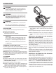
FEATURES BLOWS PER MINUTE KNOW YOUR IMPACT DRIVER See Figure 1. Before attempting to use this product, familiarize yourself with all operating features and safety rules. This tool features an impact speed of 0-3,100 Blows Per Minute (BPM). Blows Per Minute are the number of impacts per minute. COUPLER RIGHT ANGLE DESIGN Quickly and easily change bits without the need for separate tools. Right angle design allows you to drive screws in tight places.
OPERATION WARNING: Do not allow familiarity with your tool to make you careless. Remember that a careless fraction of a second is sufficient to inflict severe injury. WARNING: Always wear safety goggles or safety glasses with side shields when operating tools. Failure to do so could result in objects being thrown into your eyes resulting in possible serious injury.
OPERATION LED FUNCTION OF CHARGER See Figure 3.
OPERATION INSTALLING BITS See Figure 4. n Lock the paddle switch on the driver by placing the direction of rotation (forward-reverse) selector in center lock out position. PULL COUPLER FORWARD BIT n Remove the battery pack from the driver. 3 RELEASE COUPLER 1 INSERT BIT n Pull the coupler away from the driver (1). 2 n Insert driver bit to be used into the coupler (2). n Release the coupler (3). n Pull on the bit to make sure it is secured in the coupler.
OPERATION TO REMOVE BATTERY PACK TO TURN ON See Figure 6. n Locate the latches on the side of the battery pack and depress both sides to release the battery pack from the driver. TO TURN OFF DIRECTION OF ROTATION SELECTOR (FORWARD / REVERSE / LOCK-OUT) n Remove the battery pack from the driver. FORWARD REVERSE PADDLE SWITCH DEPRESS LATCHES TO RELEASE BATTERY PACK Fig. 7 Fig. 6 PADDLE SWITCH See Figure 7. n To turn your driver ON, depress the paddle switch. To turn it OFF, release the paddle switch.
OPERATION RIGHT ANGLE DESIGN WARNING: See Figures 9 - 10. Battery tools are always in operating condition. Therefore, switch should always be locked when not in use or carrying at your side. T � he impact driver features a right angle head design to reach into tight areas. WARNING DRIVING OR REMOVING SCREWS Hold tool by insulated gripping surfaces when performing an operation where the screw may contact hidden wiring.
MAINTENANCE WARNING: WARNING: When servicing use only iden ti cal RIDGID replacement parts. Use of any other parts may create a hazard or cause product damage. Do not at any time let brake fluids, gasoline, petroleum-based products, penetrating oils, etc., come in contact with plastic parts. Chemicals can damage, weaken or destroy plastic which may result in serious personal injury. WARNING: Only the parts shown on the parts list are intended to be repaired or replaced by the customer.
NOTES 16
WARRANTY RIDGID® HAND HELD AND STATIONARY POWER TOOL 3 YEAR LIMITED SERVICE WARRANTY WHAT IS NOT COVERED Proof of purchase must be presented when requesting warranty service. This warranty applies only to the original purchaser at retail and may not be transferred.
OPERATOR’S MANUAL 12 VOLT 1/4 in. IMPACT DRIVER RIGHT ANGLE R82233 Customer Service Information: For parts or service, contact your nearest RIDGID authorized service center. Be sure to provide all relevant information when you call or visit. For the location of the authorized service center nearest you, please call 1-866-539-1710 or visit us online at www.ridgid.com. The model number of this tool is found on a plate attached to the motor housing. Please record the serial number in the space provided below.