OPERATOR’S MANUAL 1/2 in., 18 VOLT HAMMER DRILL R8411503 Your hammer drill has been engineered and manufactured to our high standards for dependability, ease of operation, and operator safety. When properly cared for, it will give you years of rugged, trouble-free performance. WARNING: To reduce the risk of injury, the user must read and understand the operator’s manual before using this product. Thank you for buying a RIDGID product.
TABLE OF CONTENTS Introduction .....................................................................................................................................................................2 General Safety Rules ................................................................................................................................................... 3-4 Specific Safety Rules .................................................................................................................
GENERAL SAFETY RULES Do not overreach. Keep proper footing and balance at all times. Proper footing and balance enable better control of the tool in unexpected situations. Use safety equipment. Always wear eye protection. Dust mask, non-skid safety shoes, hard hat, or hearing protection must be used for appropriate conditions. Do not wear loose clothing or jewelry. Contain long hair. Loose clothes, jewelry, or long hair can be drawn into air vents. Do not use on a ladder or unstable support.
GENERAL SAFETY RULES SERVICE When servicing a tool, use only identical replacement parts. Follow instructions in the Maintenance section of this manual. Use of unauthorized parts or failure to follow Maintenance Instructions may create a risk of shock or injury. Tool service must be performed only by qualified repair personnel. Service or maintenance performed by unqualified personnel may result in a risk of injury.
SAFETY RULES FOR CHARGER chemicals that can damage, weaken, or destroy plastic. WARNING! READ AND UNDERSTAND ALL INSTRUCTIONS. Failure to follow all instructions listed below, may result in electric shock, fire and/or serious personal injury. An extension cord should not be used unless absolutely necessary. Use of improper extension cord could result in a risk of fire and electric shock. If extension cord must be used, make sure: a.
SYMBOLS Some of the following symbols may be used on this tool. Please study them and learn their meaning. Proper interpretation of these symbols will allow you to operate the tool better and safer.
SYMBOLS The following signal words and meanings are intended to explain the levels of risk associated with this product. SYMBOL SIGNAL MEANING DANGER: Indicates an imminently hazardous situation, which, if not avoided, will result in death or serious injury. WARNING: Indicates a potentially hazardous situation, which, if not avoided, could result in death or serious injury. CAUTION Indicates a potentially hazardous situation, which, if not avoided, may result in minor or moderate injury.
FEATURES PRODUCT SPECIFICATIONS Chuck ...........................................................1/2 in. Keyless Blows per minute ........................... 0-7,200/0-25,600 BPM Motor .................................................................. 18 Volt DC Clutch ................................................................ 24 Position Switch.............................. VSR (Variable Speed Reversible) Torque................................................................... 585 in.lb.
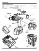
FEATURES the direction of bit rotation. Setting the switch trigger in the OFF (center lock) position helps reduce the possibility of accidental starting when not in use. KNOW YOUR HAMMER DRILL See Figure 1. The safe use of this product requires an understanding of the information on the tool and in this operator’s manual as well as a knowledge of the project you are attempting. Before use of this product, familiarize yourself with all operating features and safety rules.
OPERATION WARNING: Do not allow familiarity with tools to make you careless. Remember that a careless fraction of a second is sufficient to inflict severe injury. WARNING: Always wear safety goggles or safety glasses with side shields when operating tools. Failure to do so could result in objects being thrown into your eyes resulting in possible serious injury. WARNING: Do not use any attachments or accessories not recommended by the manufacturer of this tool.
OPERATION LED FUNCTION OF CHARGER See Figure 3. LED INDICATOR BATTERY PACK RED LED GREEN LED ACTION Power Without battery pack ON OFF Ready to charge battery pack Evaluate Hot battery pack Flashing OFF When battery pack reaches cooled temperature, charger begins fast charge mode. Evaluate Cold battery pack Flashing OFF When battery pack reaches warmed temperature, charger begins fast charge mode.
OPERATION TO INSTALL BATTERY PACK See Figure 4. Lock the switch trigger on the drill by placing the direction of rotation (forward/reverse/center lock) selector in center position. Place the battery pack in the drill. Align the raised rib on the battery pack with the groove inside the drill. Make sure the latches on each side of your battery pack snap in place and battery pack is secured in the drill before beginning operation.
OPERATION DIRECTION OF ROTATION SELECTOR (FORWARD/REVERSE/CENTER LOCK) See Figure 5. The direction of bit rotation is reversible and is controlled by a selector located above the switch trigger. With the drill held in normal operating position, the direction of rotation selector should be positioned to the left of the switch trigger for drilling. The drilling direction is reversed when the selector is to the right of the switch trigger.
OPERATION TO DECREASE TORQUE ADJUSTABLE TORQUE CLUTCH This product is equipped with an adjustable torque clutch for driving different types of screws into different materials. The proper setting depends on the type of material and the size of screw you are using. ADJUSTING RING ADJUSTING TORQUE See Figure 8. There are twenty-four torque indicator settings located on the front of the drill. Rotate the adjusting ring to the desired setting.
OPERATION INSTALLING BITS See Figure 10. Lock the switch trigger by placing the direction of rotation selector in the center position. DRILL BIT UNLOCK (RELEASE) KEYLESS CHUCK Open or close the chuck jaws to a point where the opening is slightly larger than the bit size you intend to use. Also, raise the front of the drill slightly to keep the bit from falling out of the chuck jaws. Insert the drill bit. CHUCK JAWS WARNING: Make sure to insert the drill bit straight into the chuck jaws.
OPERATION 360° ROTATION USING THE AUXILIARY HANDLE ASSEMBLY See Figure 13 An auxiliary handle assembly is packed with the drill for ease of operation and to help prevent loss of control. The handle can be rotated 360°, and it can also be mounted on the opposite side for left hand use. To adjust the auxiliary handle assembly, Loosen the handle assembly by turning the handle counterclockwise. Rotate the handle assembly to the desired operating position.
OPERATION WOOD DRILLING� MASONRY DRILLING Select normal drilling mode.� Turn hammer mode ring to the hammer drill icon to select hammer mode.� For maximum performance, use high speed steel bits for wood drilling.� For maximum performance, use carbide-tipped masonry impact bits when drilling holes in brick, tile, concrete, etc. Begin drilling at a very low speed to prevent the bit from slipping off the starting point. Increase the speed as the drill bit bites into the material.
MAINTENANCE GENERAL MAINTENANCE WARNING: Avoid using solvents when cleaning plastic parts. Most plastics are susceptible to damage from various types of commercial solvents and may be damaged by their use. Use clean cloths to remove dirt, dust, oil, grease, etc. When servicing use only identical RIDGID replacement parts. Use of any other parts may create a hazard or cause product damage. WARNING: WARNING: Do not at any time let brake fluids, gasoline, petroleum-based products, penetrating oils, etc.
MAINTENANCE CHUCK REMOVAL MALLET See Figures 15 - 17. The chuck may be removed and replaced by a new one. CHUCK JAWS Lock the switch trigger by placing the direction of rotation selector in center position. Insert a 5/16 in. or larger hex key into the chuck of the drill and tighten the chuck jaws securely. Tap the hex key sharply with a mallet in a clockwise direction. This will loosen the screw in the chuck for easy removal. Open the chuck jaws and remove the hex key.
NOTES 20
WARRANTY RIDGID® HAND HELD AND STATIONARY POWER TOOL 3 YEAR LIMITED SERVICE WARRANTY WHAT IS NOT COVERED Proof of purchase must be presented when requesting warranty service. This warranty applies only to the original purchaser at retail and may not be transferred.
OPERATOR’S MANUAL 1/2 in., 18 VOLT HAMMER DRILL R8411503 Customer Service Information: For parts or service, contact your nearest RIDGID authorized service center. Be sure to provide all relevant information when you call or visit. For the location of the authorized service center nearest you, please call 1-866-539-1710 or visit us online at www.ridgid.com. The model number of this tool is found on a plate attached to the motor housing. Please record the serial number in the space provided below.