UNINTERRUPTIBLE POWER SUPPLY - ON LINE 700 VA ÷ 3000 VA User’s manual
GB SAFETY GB This part of the manual contains precautions that must absolutely be followed as they relate to SAFETY. Installation ¾ Connect the UPS system only to an earthed shockproof socket outlet. ¾ The building wiring socket outlet (shockproof socket outlet) must be easily accessible and close to the UPS system. ¾ Please use only VDE-tested, CE-marked mains cable (e.g. the mains cable of your computer) to connect the UPS system to the building wiring socket outlet (shockproof socket outlet).
GB USER’S MANUAL GB 5
INTRODUCTION Thanks you for choosing our product. Our manufacturer are renowned specialists in the development and production of uninterruptible power supplies (UPS). The UPS in this range are high quality products, designed and built with care in order to give you the best performance. This equipment can be installed by anyone, subject to CAREFULLY AND THOROUGHLY READING THIS MANUAL. The manual contains detailed instructions on how to use and install the UPS.
CONTENTS PRESENTATION 8 VIEW OF THE UPS 9 Front Views 9 Rear Views 10 VIEW OF LED INDICATOR PANEL 12 INSTALLATION AND USE 13 OPENING THE PACKAGING AND CHECKING THE CONTENTS 13 CONNECTIONS AND SWITCHING ON FOR THE FIRST TIME 14 Connection to the Net/Tel protection device 14 SWITCHING ON FROM MAINS POWER 14 SWITCHING ON FROM BATTERY 15 SWITCHING OFF THE UPS 15 LED INDICATOR PANEL 16 OVERLOADS ON THE UPS 17 COMMUNICATION PORTS 18 RS232 Connector 18 Communication Slot 19 SOFTW
PRESENTATION The new Dialog Plus family of UPS has been designed to offer versatility and reliability. They use ON LINE technology, which means that the AC power for the load is converted to DC and then back to AC again to ensure a perfectly sinusoidal output, the frequency and voltage of which are established by microprocessor digital control and are independent of the input power source.
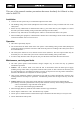
PRESENTATION VIEW OF THE UPS Front Views Models: 700-1000-1500VA Models: 2000-3000VA 1. LED indicator panel 2. ON button 3.
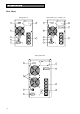
PRESENTATION Rear Views Dialog Plus 70 1 Dialog Plus 100 / 100 ER / 150 7 1 7 8 2 2 3 3 6 6 4 4 5 5 Dialog Plus 200 1 7 8 2 6 4 5 10 3
PRESENTATION Dialog Plus 200 ER 1 Dialog Plus 300 / 300 ER 7 1 7 8 8 9 2 2 6 10 6 3 3 4 4 5 5 1. 2. 3. 4. 5. RS232 serial communication port Cooling fans Telephone/modem protection Input thermal protection Mains power socket 6. 7. 8. 9. 10.
PRESENTATION VIEW OF LED INDICATOR PANEL 1 2 3 4 5 1 Load level indicator 2 Battery level indicator 3 Mains mode indicator 4 Battery mode indicator / Battery low indicator 5 Battery failure indicator 6 Load powered by bypass indicator 7 “Fault/Stand-by” indicator 12 6 7
INSTALLATION AND USE OPENING THE PACKAGING AND CHECKING THE CONTENTS The first thing to do after opening the packaging is to check the contents The packaging should contain the following: UPS IEC 10A(or 16A) Power cord 2 IEC 10A connection cables RS232 serial cable IEC 16A Power cord set (only for model 3000VA) User manual + CD-ROM with software User's manual Connector for battery expansion kit (only on ER models) 13
INSTALLATION AND USE This chapter describes the operations to be carried out to prepare the UPS. WARNING: the instructions below should be followed scrupulously for your personal safety and that of the product. BEFORE CARRYING OUT THE FOLLOWING SEQUENCE OF OPERATIONS, MAKE SURE THAT THE UPS IS COMPLETELY SWITCHED OFF AND IS NOT CONNECTED TO THE MAINS OR TO ANY LOAD. CONNECTIONS AND SWITCHING ON FOR THE FIRST TIME 1) Connect the power cable supplied with the UPS to the IEC input socket.
INSTALLATION AND USE SWITCHING ON FROM BATTERY 1) When mains power is not available, press the ON button for about 1 second (until a beep sounds and then release it). All the icons on the indicator panel light up for 1 second and a beep sounds. A test is run on the batter voltage and, if all is normal, only the “Battery mode”, load level and battery level indicators stay on accompanied by an intermittent beep. Switch on all the loads connected to the UPS.
INSTALLATION AND USE LED INDICATOR PANEL This chapter gives a detailed description of all LED indicator panel. ICON STATUS DESCRIPTION Red / Steady Indicates an fault Red / Flashing The UPS is in stand-by mode Green / Steady The UPS is operating on mains power Green / Flashing The UPS is operating off the bypass The voltage input is out of the accepted range Green / Steady The UPS is operating in battery mode and will beep at regular intervals.
INSTALLATION AND USE Table 2 Battery level 1 2 Battery LED bar 3 4 5 0%~20% ● 20%~40% ● ● 40%~60% ● ● ● 60%~80% ● ● ● ● 80%~100% ● ● ● ● ● 1 2 Battery LED bar 3 4 5 Table 3 Input Voltage 190V~200V ● 200V~230V ● ● 230V~250V ● ● ● 250V~260V ● ● ● ● >260V ● ● ● ● ● 100 ! Tab.
INSTALLATION AND USE After switching over to the bypass due to overloading, the UPS powers the loads off mains power and a continuous alarm will sound. By reducing the load within the 102% threshold, the UPS returns to normal operating mode. When the overload level is too high, the input thermal protection is activated and the UPS will be completely shutdown.
INSTALLATION AND USE Communication Slot All UPS come with an expansion slot for optional communication boards so that the unit is compatible with the main communication standards. Some examples: • Serial port duplexer • Ethernet network agent with TCP/IP, HTTP and SNMP protocols • RS232 + RS485 port with JBUS / MODBUS protocol For more details on the options available, visit the manufacturer’s web site.
INSTALLATION AND USE UPS CONFIGURATION The following table lists all the possible configurations available so as to best adapt the UPS to user requirements. The configuration may be modified only by using the configuration software provided. FUNCTION DESCRIPTION PREDEFINED Automatic Restart Automatic restart when mains power returns Enabled. Battery low alarm Remaining battery charge level setting for the battery low alarm 3 min. Output frequency Allows the user to select the output frequency.
ALARMS AND INDICATORS The following table describes the light and audio indicators that appear/sound during normal UPS operation. Load level Battery level Mains LED UPS Status 1 2 3 4 5 1 2 3 4 Battery LED 5 Bypass LED Battery failure LED Failure/ Fault LED Audio Alarm ♦ Standby Bypass Load level Battery level ♦ Line Load level Battery level ● Battery normal Load level Battery ● ● 1 beep every 4s ♦ 1 beep per sec.
ALARMS AND INDICATORS The following table describes the light and audio signals that appear/sound to indicate a fault. Load level Battery level UPS Status 1 2 3 4 5 1 2 3 4 5 Alarm phase Mains overload Mains LED Battery LED Bypass LED Battery failure LED Failure/ Fault LED 2 beeps per sec.
PROBLEM SOLVING Very often incorrect UPS operation is not caused by a fault but by common problems, difficulties or carelessness. The table below gives some useful information to help the user solve the most frequent problems. PROBLEM POSSIBLE CAUSE THE POWER CABLE IS NOT CONNECTED THE DISPLAY PANEL DOES NOT LIGHT UP THE PANEL IS ON BUT THE LOAD IS NOT POWERED THE UPS IS IN BATTERY MODE EVEN THOUGH MAINS POWER IS AVAILABLE Check that the power cable is connected correctly.
1- TECHNICAL SPECIFICATIONS MODELS INPUT Nominal voltage (±1.
TECHNICAL SPECIFICATIONS MODELS INPUT Nominal Voltage (±1.
TECHNICAL SPECIFICATIONS MODELS INPUT Nominal voltage (±1.
TECHNICAL SPECIFICATIONS (1) at nominal load, minimum voltage of 164 Vac, battery charging (2) at nominal load, nominal voltage of 230Vac, battery charging (3) Second appendix M5 of the EN50091-1-1 specifications (4) Mains/Battery at load: 0% -100% (5) at Mains / battery / mains at resistive load: 0% / 100% / 0% (6) If the mains frequency falls within ± 5% of the selected value, the UPS is synchronised with mains voltage.
UPS MANUFACTURING s.r.l. I – 37048 S.Pietro di Legnago (VR) Italy – Viale Europa, 7 – ZAI Tel. +39 0442 635811 – Fax +39 0442 629098 www.riello-ups.com - riello@riello-ups.