Installation & Operating Manual Single stage operation forced draught natural gas/propane burner The following pages contain information, descriptions and diagrams for the proper installation and wiring of the burner. Please read carefully before attempting final installation. This manual is to remain with the final installation designation.
GB TABLE OF CONTENTS Installation instructions and owner's handbook . . . . . . . . . . . . . . . . . . . . . . . . . . . . . . . . . . . . . . . . . . . . . . . . . . . 2 General information . . . . . . . . . . . . . . . . . . . . . . . . . . . . . . . . . . . . . . . . . . . . . . . . . . . . . . . . . . . . . . . . . . . . . . . 3 Step by step procedure. . . . . . . . . . . . . . . . . . . . . . . . . . . . . . . . . . . . . . . . . . . . . . . . . . . . . . . . . . . . . . . . . . . . .
GB INSTALLATION INSTRUCTIONS AND OWNER'S HANDBOOK CAUTION: All gas burners MUST be installed by trained and licensed technicians. WARNING: Installation of this burner must conform with local codes or, in the absence of local codes, with the Standard for the Installation of Domestic Gas Conversion Burners, ANSI Z21.8-1984, and Addendum, Z21.8a-1989, and the National Fuel Gas code, ANSI Z223.1-1984, and CAN/CGA B149.1 &.2.
GB GENERAL INFORMATION Your Riello gas burner comes to you completely assembled and factory wired, ready for installation. Models equipped with the short combustion head have a fixed flange, which bolts directly to the front of the appliance. When equipped with the long combustion head, the burner comes with a universal flange, which when bolted to the appliance, allows the burner to be adjusted for exact positioning in the combustion zone.
GB SERIAL NUMBER IDENTIFICATION Your Riello burner may have been manufactured in more than one location and therefore there are two possible serial number identification. The Riello 9 character serial number, example, 06 01 12345, is identified as follows: 06 = Last two digits of the year of manufacture; 01 = Week of manufacture; 12345 = Increment of 1 for each burner produced – specific to product code – reset to zero each January 1st.
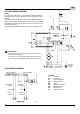
GB BURNER DIMENSIONS G G1 ° 60 45° 30° F 7 3/32” - 180 mm 3 31/32” 101 mm J I E A H B 5 1/2”-140mm D7332 D 7 1/2” - 190 mm C Model 400 A B C D inches 10 5/16 12 1/64 2 13/32 1 19/64 mm 262 305 61 33 8 15/32” - 215 mm E D7351 F G G1 H I J /4 13 5/8 4 21/64 10 33/64 4 1/8 5 19/32 8 1/32 19 346 110 267 105 142 204 3 NOTE: Actual available insertion length must be measured from tip of end cone to face of mounting gasket.
GB TYPICAL GAS TRAIN LAYOUT THE GAS TRAIN LEAVES THE FACTORY SET AT 3.5” wc. ATTENTION This gas train scope of supply meets the minimum controls requirements according to CSA Canada and USA regulations. Any additional requirements needed to meet local codes are the responsibility of others.
GB INSTALLING THE BURNER A) B) 1) 2) 3) 1 3 2 Burner Chassis Combustion Head Assembly Locking Nut Mounting Plate surface Insulation Gasket Separate the combustion head of the burner from the chassis (A) by removing the locknut (1). Install the combustion head into the boiler. Typical insertion depth, the front edge of the combustion head is flush with the inside surface of the appliance mounting surface (2).
GB INSTALLATION OF SEDIMENT TRAP AND BURNER SUPPLY Gas piping to the burner must be 1/2-inch minimum. Install only a full-ported shutoff valve. The valve must be located outside the appliance jacket, and the pressure gauge port must be accessible. PRESSURE TEST-OVER 1/2 PSIG. The appliance and its individual shutoff valve must be disconnected from the gas supply piping system during any pressure testing of the system at a test pressure in excess of 1/2 PSIG.
GB FACTORY WIRING DIAGRAM NOTE: The SAFETY SWITCH on the 525SE CONTROL BOX is equipped with a contact allowing remote sensing of burner lockout. The electrical connection is located on the CONTROL BOX terminal 4 as indicated. Should burner lockout occur, the 525SE CONTROL BOX will supply a power source of 120 Vac to the connection terminal. The maximum allowable current draw on this terminal is 1A.
GB SETTING UP THE BURNER After burner output has been determined, use TABLE 1 below AS AN INITIAL GUIDE for burner settings. All settings in this table were obtained under the following conditions. O O 0 (zero) draft in the combustion zone; Standard lab test boiler; O O Inlet gas pressure range as in table 1; Steady state (HOT) operating conditions. NATURAL GAS Gas inlet pressure range “wc 5.0 - 7.0 Orifice Marking C1 C2 C3 C4 C5 C6 Manifold gas pressure “wc 3.
GB The integrated control system is self-checking. The cycle from start up to flame establishment, takes approximately 70 seconds. The burner will go into lockout under the following circumstances: a) Burner fails to ignite; b) The ionization probe is grounded; c) Opening of the air pressure switch or the normally open contacts of the air pressure switch not making. Should overheating of the appliance occur, shut off the manual gas valve to the burner.
GB ORIFICE INSTALLATION AND COMBUSTION HEAD SETTING A proper orifice (C) has to be installed in the combustion head gas line, according to TABLE 1. A complete set of gas orifices is delivered with the burner packaging as equipment. The burner leaves the factory with the A3 orifice already installed. In case another orifice has to be installed, following the instructions below. D E G To remove the drawer assembly from the manifold (B), follow the procedure below: 1) Disconnect 24v leads at the gas valve.
GB PRESSURE WORKING CHART The chart below shows effects of pressure in the combustion zone on the minimum/maximum burner outputs. In this example, with a maximum operating pressure of 0.6 inches water column in the combustion zone, you will be able to obtain a maximum of 370,000 Btu/h burner output. Pressure PRESSURE WORKING CHART Natural and Propane Gas In/wc 4.0 3.0 2.0 1.0 0.0 49.8 170,000 61.5 73.8 85.0 96.7 108.4 120.
GB COMBUSTION CHECKS CO2 It is advisable not to exceed a measured reading of 10% CO2 for Natural Gas or 12% CO2 for Propane Gas. CO For safety reasons, the value of .02% (200ppm) free air sample must not be exceeded. IONIZATION CURRENT The minimum amount of current necessary for the control box to operate properly is 3 micro Amps DC.
GB 4) The burner continues to repeat the starting cycle without going into lockout. This is a very specific situation caused when gas pressure in the gas main lines is very close to the value at which the gas pressure switch has been set. This can be corrected by resetting the gas pressure switch to a lower level. The gas pressure switch, if required, may be supplied, or may have to be field installed. 5) The burner does not go through prepurge, and the control module goes to lockout.
GB PROPANE BURNER APPLICATION The burner leaves the factory to run on natural gas. It is available a kit, on request, that allows the burner to run on propane. TECHNICAL FEATURES The thermal output and operating range of burners converted to use propane are the same as for burners running on natural gas. GAS Family 3: Net calorific value: 24 - 34 kWh/m3 21,000 ÷ 29,300 kcal/m3 Min. pressure 25 - max. 50 mbar. Fig.
GB PROPANE SETTING UP THE BURNER After burner output has been determined, use TABLE below AS AN INITIAL GUIDE for burner settings. All settings in this table were obtained under the following conditions. O O 0 (zero) draft in the combustion zone; Standard lab test boiler; O O Inlet gas pressure range as in table; Steady state (HOT) operating conditions.
GB SPARE PARTS 18
GB SPARE PARTS LIST No. CODE DESCRIPTION No.
GB 2165 Meadowpine Blvd. Mississauga,On L5H 3R2 Phone: 905-542-0303 Toll Free: 800-387-3898 Fax: 905-542-1525 35 Pond Park Rd. Hingham, MA 02043 Phone: 781-749-8292 Toll Free: 800-992-7637 Fax: 781-740-2069 BURNER START- UP FORM * Appliance: Burner S/N.
35 Pond Park Road Hingham, MA 02043 Phone 781-749-8292 Toll Free 800-992-7637 Fax 781-740-2069 www.riellousa.com 2165 Meadowpine Blvd Mississauga, ON L5N 6H6 Phone 905-542-0303 Toll Free 800-387-3898 Fax 905-542-1525 www.riellocanada.