OPENPATH ACCESS CONTROL SYSTEM INSTALLATION GUIDE V1.
Openpath Access Control System Installation Guide GETTING STARTED ADDITIONAL RESOURCES PRIOR TO INSTALLATION Installation NETWORK REQUIREMENTS SELECTING A BACKUP BATTERY MOUNTING INSTRUCTIONS RECOMMENDED CONFIGURATION WIRING WITH THE 12/24V POWER SUPPLY WIRING THE REX WITH THE DOOR STRIKE WIRING THE REX WITH THE ELECTROMAGNETIC LOCK WIRING FAIL SAFE AND FAIL SECURE LOCKING HARDWARE WIRING TO LEGACY PANELS WIRING THE OPENPATH ELEVATOR BOARD Troubleshooting LEGACY WIRING ACU LEDS READER LEDS RESETTING THE ACU
Openpath Access Control System Installation Guide GETTING STARTED This Installation Guide explains how to install and configure Openpath Smart Hubs (ACUs) and Openpath Smart Readers as part of an Openpath Access Control system.
NOTE: If using an external DNS server, outbound UDP port 53 must also be open. To support Wi-Fi unlocking from the mobile app, the Smart Hub’s inbound TCP port 443 must be available from within the LAN. Inbound port forwarding on the router, firewall, or NAT device is not required. SELECTING A BACKUP BATTERY While not required, Openpath recommends having a backup battery in the case of power outages. The size of battery depends on your setup and how long you want to power the system.
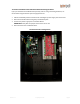
8. Reinstall the enclosure’s cover, if removed in step 1. WARNING: Only connect the Controller Board to 12V. Over voltage can damage the board. To install a standalone Controller Board with 24V locking hardware: If you purchased the Controller Board separately and are using 24V locking hardware, we recommend using the LifeSafety Power E1 enclosure, FPO75 power supply (or FPV4 power supply), B100 secondary power supply, and C4 power control module. 1.
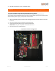
To install a standalone Controller Board with 12V locking hardware: If you purchased the Controller Board separately and are using 12V locking hardware, we recommend using the FPV4-E1 power supply/enclosure. 1. Follow all LifeSafety Power instructions for installing the power supply in the enclosure. 2. Mount the Controller Board using the provided back plate. 3. Connect the power supply to the Controller Board. IMPORTANT: Verify that the jumper on the FPV4 is set to 12V. 4.
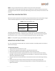
RECOMMENDED CONFIGURATION Openpath readers and ACUs communicate via RS-485. The following wire types are compatible, listed in the order of preference which impacts distance.
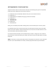
WIRING WITH THE 12/24V POWER SUPPLY Version 1.
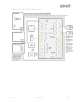
WIRING THE REX WITH THE DOOR STRIKE Version 1.
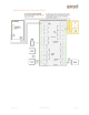
WIRING THE REX WITH THE ELECTROMAGNETIC LOCK Version 1.
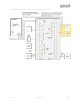
WIRING FAIL SAFE AND FAIL SECURE LOCKING HARDWARE Fail safe and fail secure are ways of configuring locking hardware: ● Fail safe hardware unlocks when power is interrupted ● Fail secure hardware locks when power is interrupted Version 1.
WIRING TO LEGACY PANELS To support a legacy access control system, install the ACU between the Openpath readers and the legacy panel, with the ACU Wiegand port configured as output to the legacy panel. Replace low frequency (LF) Wiegand readers with LF Openpath readers and high frequency (HF) Wiegand readers with HF Openpath readers.
WIRING THE OPENPATH ELEVATOR EXPANSION MODULE Version 1.
Troubleshooting LEGACY WIRING ACU LEDS READER LED PROVISIONING THE ACU RESETTING THE ACU LEGACY WIRING Sometimes legacy wiring (unshielded and straight through, rather than shielded twisted pair, often 22-6) results in slower connections and dropped packets between the Openpath Reader and Smart Hub. To remedy this, you can switch GND and VIN with +B and -A connections on the ACU and readers to ensure the data pair (+B and -A) are using the alternate pair of legacy wires.
● ● ● The four RELAY LEDs indicate when the relays are activated The STATUS LED in the center of the ACU indicates that the ACU has been configured with firmware. It will flash green when Identify is pressed in the Control Center.
PROVISIONING THE ACU Provisioning the ACU means registering it in the online portal and getting it up and running with the latest firmware. ACUs are shipped already provisioned, but below are instructions for this process in the case of RESETTING THE ACU. To provision the ACU: 1. Connect the ACU to the Internet via Ethernet 2. Press the ADMIN BUTTON 3. On a computer or mobile phone on the same network as the ACU, go to https://control.openpath.com 4. Log in with your administrative login 5.
Regulatory All national and local electrical codes apply.
Warnings ● ● ● Disconnect power before servicing Do not plug into an outlet controlled by an on/off switch Powering power supply with 230V requires jumper modification, see power supply data sheet for more information Version 1.
Technical Specifications Smart Hub with 12/24V Supply (OP-SH-24V) 120V, 0.7A or 230V, 0.3A, 50/60 Hz Smart Readers (OP-RLF-STD, OP-RHF-STD, OP-RLF-MULB, OP-RHF-MULB) 12VDC, 0.25A OP-RLF-STD/MULB: FCC ID: 2APJVOPRLF OP-RHF-STD/MULB: FCC ID: 2APJVOPRHF Standalone ACU Board (OP-4ECTR) 10-14VDC, 1A Elevator Board (OP-16EM) 12-24VDC, 0.35A Version 1.