USER GUIDE AgGPS® RTK Base 450/900 GPS Receiver
USER GUIDE AgGPS® RTK Base 450/900 GPS Receiver Version 3.
Corporate Office Trimble Navigation Limited 935 Stewart Drive Sunnyvale, CA 94085 USA www.trimble.com Agriculture Business Area Trimble Navigation Limited 10355 Westmoor Drive Suite #100 Westminster, CO 80021 USA www.trimble.com Email: trimble_support@trimble.com Legal Notices © 2006–2007, Trimble Navigation Limited. All rights reserved.
Restriction of Use of Certain Hazardous Substances in Electrical and Electronic Equipment (RoHS) The following statement only applies to the AgGPS RTK Base GPS receiver (no internal radio and 450 MHz internal radio models only) This Trimble product complies in all material respects with DIRECTIVE 2002/95/EC OF THE EUROPEAN PARLIAMENT AND OF THE COUNCIL of 27 January 2003 on the restriction of the use of certain hazardous substances in electrical and electronic equipment (RoHS Directive) and Amendment 2005/
4 AgGPS RTK Base 450/900 GPS Receiver User Guide
Safety Information Safety Information Before you use your Trimble® RTK Base GPS receiver, make sure that you have read and understood all safety requirements. Regulations and safety The receivers contain an internal radio-modem and can send signals through Bluetooth® wireless technology or through an external data communications radio. Regulations regarding the use of the 450 MHz radio-modems vary greatly from country to country.
Safety Information Exposure to radio frequency radiation For 450 MHz radio Safety. Exposure to RF energy is an important safety consideration. The FCC has adopted a safety standard for human exposure to radio frequency electromagnetic energy emitted by FCC regulated equipment as a result of its actions in General Docket 79-144 on March 13, 1986. Proper use of this radio modem results in exposure below government limits.
Safety Information For Bluetooth radio The radiated output power of the internal Bluetooth wireless radio is far below the FCC radio frequency exposure limits. Nevertheless, the wireless radio shall be used in such a manner that the Trimble receiver is 20 cm or further from the human body. The internal wireless radio operates within guidelines found in radio frequency safety standards and recommendations, which reflect the consensus of the scientific community.
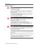
Safety Information Battery safety 8 C WARNING – Do not damage the rechargeable Lithium-ion battery. A damaged battery can cause an explosion or fire, and can result in personal injury and/or property damage. To prevent injury or damage: – Do not use or charge the battery if it appears to be damaged. Signs of damage include, but are not limited to, discoloration, warping, and leaking battery fluid. – Do not expose the battery to fire, high temperature, or direct sunlight.
Contents Safety Information . . . . . . . . . . . . . . . . . . . . . . . . . 5 Regulations and safety . . . . . . . . . . . Type approval . . . . . . . . . . . . . . . . Exposure to radio frequency radiation . For 450 MHz radio . . . . . . . . . For license-free 900 MHz radio . For Bluetooth radio . . . . . . . . Installing antennas . . . . . . . . . . . . . Battery safety. . . . . . . . . . . . . . . . . 1 . . . . . . . . . . . . . . . . . . . . . . . . . . . . . . . . . . . . . . . . . . . . . . .
Contents Charging the Lithium-ion battery . . . . . . . . . . . . . . . . . . . . . . . . . . . . . 24 Storing the Lithium-ion battery . . . . . . . . . . . . . . . . . . . . . . . . . . . . . . 25 Removing the Lithium-ion battery . . . . . . . . . . . . . . . . . . . . . . . . . . . . 25 4 Setup Guidelines . . . . . . . . . . . . . . . . . . . . . . . . . .27 Base station operation guidelines . . . . . . . . . . . . . . . . . . . . . . . . . . . . . 28 Base station components. . . . . . . . . . . . . .
Contents Scenario Four: Repeat visit to a site with AutoBase Warning turned on 53 The AutoBase process . . . . . . . . . . . . . . . . . . . . . . . . . . . . . . . . . . . . 55 8 Default Settings . . . . . . . . . . . . . . . . . . . . . . . . . .57 Default receiver settings . . . . . . . . . . . . . . . . . . . . . . . . . . . . . . . . . . . 58 Resetting the receiver to factory defaults . . . . . . . . . . . . . . . . . . . . . . . . 58 9 Specifications . . . . . . . . . . . . . . . . . . . . . . .
Contents 12 AgGPS RTK Base GPS Receiver User Guide
CHAPTER 1 Introduction Welcome to the AgGPS RTK Base GPS Receiver User Guide. This manual describes how to set up and use the AgGPS® RTK Base 450 and the AgGPS RTK Base 900 GPS receivers from Trimble®. Even if you have used other Global Positioning System (GPS) products before, Trimble recommends that you spend some time reading this manual to learn about the special features of this product. If you are not familiar with GPS, visit the Trimble website (www.trimble.
1 Introduction Related information Sources of related information include the following: • Trimble training courses – Consider a training course to help you use your GPS system to its fullest potential. For more information, go to the Trimble website at www.trimble.com/training.html. Technical support If you have a problem and cannot find the information you need in the product documentation, contact your local dealer. Alternatively, go to the Support area of the Trimble website (www.trimble.
CHAPTER 2 Features and Functions In this chapter: Q AgGPS RTK Base receiver features Q Use and care Q COCOM limits Q Keypad and display Q Rear connectors 2 The AgGPS RTK Base GPS receivers are ideal for both fixed and mobile base station applications. The AgGPS RTK Base receiver can be permanently installed infrastructure for individual RTK base station coverage, or it can be part of an RTK network. It is also designed for mobile applications with a quick setup and AutoBase™ technology.
2 Features and Functions AgGPS RTK Base receiver features The Trimble AgGPS RTK Base 900 and 450 receivers are easy to use RTK base stations for agricultural applications. With many time-saving features, the AgGPS RTK base receiver can be used as a mobile base or as part of a base station network. It uniquely combines a GPS receiver, RTK radio, and 10 hour battery into one small unit.
Features and Functions 2 COCOM limits The U.S. Department of Commerce requires that all exportable GPS products contain performance limitations so that they cannot be used in a manner that could threaten the security of the United States. The following limitations are implemented on this product: • Immediate access to satellite measurements and navigation results is disabled when the receiver velocity is computed to be greater than 1,000 knots, or its altitude is computed to be above 18,000 meters.
2 Features and Functions Feature Description 3 Display The receiver has a Vacuum Fluorescent Display. This display allows you to see how the receiver is operating and view the configuration settings. 4 Bluetooth antenna Location of the Bluetooth antenna. Rear connectors 1 2 5 3 Figure 2.
Features and Functions 2 Connector type Description 4 High Density DB26 • Ethernet connectivity to a 10/100 Base-T network through an RJ45 jack on a multiport adaptor (P/N 57167) • 'Slave' USB communications through the USB type B connector on the multiport adaptor (P/N 57167) • 'Host' USB communications through the USB type A connector on the 26-pin to Hirose adaptor (P/N 5665310) and Hirose to USB type A cable (P/N 73841001) • Primary power from a Trimble AC/DC power supply (P/N 59221-00) using the
2 Features and Functions 20 AgGPS RTK Base GPS Receiver User Guide
CHAPTER 3 Batteries and Power In this chapter: Q External power Q Battery safety Q Battery performance Q Charging the Lithium-ion battery Q Storing the Lithium-ion battery Q Removing the Lithium-ion battery 3 The AgGPS RTK Base GPS receiver uses an internal rechargeable Lithium-ion battery, which can be replaced only at an Authorized Trimble Service Center. The receiver can also be powered by an external power source that is connected to the Lemo or modem port.
3 Batteries and Power External power The GPS receiver uses an external power source in preference to its internal batteries. If the receiver is not connected to an external power source, or if the external power supply fails, the internal batteries are used. Battery safety The receiver is powered by a rechargeable internal Lithium-ion battery. Charge and use the battery only in strict accordance with the instructions below. C 22 WARNING – Do not damage the rechargeable Lithium-ion battery.
Batteries and Power C 3 WARNING – Avoid contact with the rechargeable Lithium-ion battery if it appears to be leaking. Battery fluid is corrosive, and contact with it can result in personal injury and/or property damage. To prevent injury or damage: – If the battery leaks, avoid contact with the battery fluid. – If battery fluid gets into your eyes, immediately rinse your eyes with clean water and seek medical attention.
3 Batteries and Power Charging the Lithium-ion battery The rechargeable Lithium-ion battery is supplied partially charged. Charge the battery completely before using it for the first time. If the battery has been stored for longer than three months, charge it before use. The internal battery charges fully in 8 hours when connected to a suitable power source. C 24 WARNING – Charge and use the rechargeable Lithium-ion battery only in strict accordance with the instructions.
Batteries and Power 3 Storing the Lithium-ion battery If you must store a Lithium-ion battery for long periods, make sure that it is fully charged before it is stored, and that you charge it at least once every three months while it is stored. Do not allow a battery that is in storage to discharge to below 5 V. A battery that reaches deep discharge level (5 V or less) cannot be recharged and must be replaced.
3 Batteries and Power 26 AgGPS RTK Base GPS Receiver User Guide
CHAPTER 4 Setup Guidelines In this chapter: Q Base station operation guidelines 4 GPS Real-Time Kinematic (RTK) operation provides centimeter-level accuracy by eliminating errors that are present in the GPS system. For all RTK operations, you require both a base station and a rover receiver.
4 Setup Guidelines Base station operation guidelines A base station consists of a receiver that is placed at a known (and fixed) position. The receiver tracks the same satellites that are being tracked by the rover receiver, at the same time that the rover is tracking them. Errors in the GPS system are monitored at the fixed (and known) base station, and a series of position corrections are computed.
4 Setup Guidelines The GPS antenna included with the AgGPS RTK Base 450/900 receiver is a Trimble Zephyr Geodetic™ Model 2 antenna. The Zephyr Geodetic Model 2 antenna has a large ground plane to eliminate multipath and can be used in both fixed (permanent) installations and mobile base station applications.
4 Setup Guidelines • Make sure that the GPS receiver does not lose power. The GPS receiver has an integrated battery, which has to be charged. To operate for the full day without loss of power at the base station, provide external power.
Setup Guidelines • 4 Do not set up the base station directly beneath or close to overhead power lines or electrical generation facilities. The electromagnetic fields associated with these utilities can interfere with GPS receiver operation.
4 Setup Guidelines • Trimble recommends that you install lightning protection equipment at permanent base station locations. Equipment should include a gas capsule lightning protector in the GPS and radio antenna feed line and appropriate safety grounding. A static dissipater near the antennas can reduce the likelihood of a direct lightning strike. Also protect any communications and power lines at building entry points.
CHAPTER 5 Setting up the Receiver In this chapter: Q Common ways to set up a base station 5 This chapter provides guidelines for setting up the AgGPSRTK Base 450/900 receiver as a base station.
5 Setting up the Receiver Common ways to set up a base station You can set up a base station in different ways depending on the application, coverage area, degree of permanence versus mobility, and available infrastructure. Before you set up a base station, please read Chapter 4, Setup Guidelines.
5 Setting up the Receiver Setting up a mobile base station: Tripod and fixed height tripod If you are repeatedly moving between fields, Trimble recommends that you use either a tripod and tribrach setup, or a fixed height tripod. The fixed height tripod is quicker and easier to set up over a control point.
5 Setting up the Receiver 4. If necessary, connect the GPS receiver to an external 12 V power supply using the crocodile clip cable. 5. Mount the external radio antenna to the bracket and connect the antenna to the receiver using the cable provided. Fixed height tripod setup A fixed height tripod setup is similar to a tripod setup, but is simplified by the central leg of the tripod, that is placed directly on the control point.
5 Setting up the Receiver Note – "Tx" indicates that the radio transmits corrections. "Rx" indicates that the receiver receives corrections. "Tx/Rx" indicates that the radio both transmits and receives corrections. If the AgGPS RTK Base receiver does not have an internal transmit radio, or you want to connect to higher power or to a secondary external transmit radio or cellular modem, use the 26-pin port, the Lemo port, or Bluetooth wireless technology.
5 Setting up the Receiver 38 AgGPS RTK Base GPS Receiver User Guide
CHAPTER 6 Configuring the Receiver Using the Keypad and Display In this chapter: Q Button functions Q Power button operations Q Home screen Q Status screens Q Configuring the receiver as a base receiver Q Configuring system settings 6 The receiver features a keypad and display (see Keypad and display, page 17) so that you can configure the receiver without using a computer.
6 Configuring the Receiver Using the Keypad and Display Button functions The AgGPS RTK Base 450/900 receiver has seven buttons on the front panel to control the receiver. Use the buttons to turn the receiver on and off and to check or change the receiver settings. Button Name Function Power Turns the receiver on and off. To turn the receiver off, hold the Power button for two seconds F Escape Returns to the previous screen or cancels changes being made on a screen.
6 Configuring the Receiver Using the Keypad and Display Power button operations Press the Power button E to turn the receiver on and off. In addition, you can tap the Power button to return to the Home screen, or hold down the Power button to perform the following operations: To … Hold the E button for … turn off the receiver two seconds The display shows a countdown timer. When the display goes blank, release the Power button.
6 Configuring the Receiver Using the Keypad and Display Home screen The Home screen is the main screen displayed on the receiver. If the receiver is displaying another screen and is left idle for 60 seconds, you are returned to the Home screen.
Configuring the Receiver Using the Keypad and Display 6 Configuring the receiver as a base receiver To set up the AgGPS RTK Base receiver as a base receiver, use AutoBase technology or the receiver keypad. The AutoBase feature automatically configures the receiver settings for you: there is no need to use the keypad. The receiver obtains a position and outputs RTK corrections on the internal radio. See Chapter 7, Automatically Setting up a Mobile Base Station Using AutoBase Technology.
6 Configuring the Receiver Using the Keypad and Display Changing the name and description of the base station In the Base Name screen: 1. Press G. When the first character of the base name begins to flash, the receiver is in Edit mode and you can change the current setting. 2. Press J 3. Press Gto move the cursor to the next character. 4. 5. 6. or K to change the value of the character. Repeat Step 2 through Step 3 to enter the name of the base station. The name can be up to 16 characters.
6 Configuring the Receiver Using the Keypad and Display Setting the reference latitude, longitude, and height of the base station In the Base Latitude screen: 1. If the base station was set with a “Here” position, press L to continue. To edit the Base Latitude setting, press G to start editing and then use the K and K arrows to change the value of the character to edit. 2. The Base Longitude screen is used to change the reference longitude of the base station.
6 Configuring the Receiver Using the Keypad and Display 4. Use the Antenna Height screen to change the height of the antenna. Press L. When the first character of the antenna height begins to flash, the receiver is in Edit mode and you can change the antenna height. The antenna height should be set to 0.00 for most applications. 5. Press J or K to change the value of the character. 6. Press Gto move the cursor to the next character. 7.
Configuring the Receiver Using the Keypad and Display 6 Configuring system settings You can use the keypad and display of the receiver to configure the following settings: • Display language • Display and input units • Baud rate, parity, data bits, and stop bits for serial ports • Display power saver • AutoBase warning To access the system settings: 1. In the Home screen, press L.
6 Configuring the Receiver Using the Keypad and Display can tell if the receiver is on or off. If an error message appears, the screen comes back on. Press L to accept the change and then press L again to move to the next screen. 12. The Autobase warning screen appears. See Chapter 7, Automatically Setting up a Mobile Base Station Using AutoBase Technology. 13. Press L to accept the change. 14. Press L again. When the Home screen appears, the system setup is complete.
CHAPTER 7 Automatically Setting up a Mobile Base Station Using AutoBase Technology In this chapter: Q AutoBase Warning Q Working with AutoBase technology Q Scenario One: First visit to a site with AutoBase Warning turned off Q Scenario Two: First visit to a site with AutoBase Warning turned on Q Scenario Three: Repeat visit to a site with AutoBase Warning turned off Q Scenario Four: Repeat visit to a site with AutoBase Warning turned on Q The AutoBase process 7 The AutoBase technology is a f
7 Automatically Setting up a Mobile Base Station Using AutoBase Technology AutoBase Warning The AutoBase Warning, when enabled, prevents the receiver from creating a new base station position and beginning operating as an RTK base station when no previous base station position exists that corresponds to the current position of the receiver.
7 Automatically Setting up a Mobile Base Station Using AutoBase Technology C 4. The receiver reviews the previous base station positions stored in the receiver. 5. The receiver does not find any base station that corresponds to the current position. 6. The receiver creates a new base station location for the current location. 7. The receiver sets the antenna height to 0. The antenna height is measured to the antenna phase center.
7 Automatically Setting up a Mobile Base Station Using AutoBase Technology Scenario Two: First visit to a site with AutoBase Warning turned on The following actions occur when you set up the base station for the first time on a point, and the AutoBase Warning is turned on: 1. You turn on the receiver. 2. The receiver begins tracking satellites. 3. The receiver determines the current position. 4. The receiver reviews the base positions stored in the receiver. 5.
7 Automatically Setting up a Mobile Base Station Using AutoBase Technology 6. C The antenna type, antenna height, and measurement method used in the previous setup of this base station are applied. CAUTION – If the antenna height is different to the previous setup, then you must enter the corrected height for the antenna (using the keypad and display) before starting measurements.
7 Automatically Setting up a Mobile Base Station Using AutoBase Technology 8. C The antenna type, antenna height, and measurement method used in the previous setup of this base station are applied. CAUTION – If the antenna height is different from the previous setup, then you must enter the corrected height for the antenna (using the keypad and display) before starting measurements.
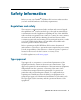
7 Automatically Setting up a Mobile Base Station Using AutoBase Technology The AutoBase process Figure 7.1 shows the AutoBase process: Power On Receiver Receiver looks for application files Do application files exist? No Yes Is AutoBase Warning On or Off? On Display AutoBase Warning Off Create new application file Save new application file with “Auto” base name Make new “Auto” application file active Figure 7.
7 Automatically Setting up a Mobile Base Station Using AutoBase Technology 56 AgGPS RTK Base GPS Receiver User Guide
CHAPTER 8 Default Settings In this chapter: Q Default receiver settings Q Resetting the receiver to factory defaults 8 All settings are stored in application files. The default application file, Default.cfg, is stored permanently in the receiver, and contains the factory default settings for the AgGPS RTK Base 450/900 receiver. Whenever the receiver is reset to its factory defaults, the current settings (stored in the current application file, Current.
8 Default Settings Default receiver settings These settings are defined in the default application file.
CHAPTER 9 Specifications In this chapter: Q General specifications Q Physical specifications Q Electrical specifications Q Communication specifications 9 This chapter details the specifications for the AgGPS RTK Base receiver. Specifications are subject to change without notice.
9 Specifications General specifications Feature Specification Keyboard and display VFD display 16 characters by 2 rows On/Off key for one button startup using AutoBase technology Escape and Enter key for menu navigation Receiver type Modular GPS receiver Antenna type Zephyr Geodetic Model 2 Also supports legacy Trimble antennas Zephyr™, Zephyr Geodetic, Micro-Centered™, Z+ Choke Ring, Rugged Micro-Centered. Physical specifications Feature Specification Dimensions (L x W x H) 24 cm (9.
9 Specifications Electrical specifications Feature Power Internal External Power consumption Specification Integrated internal battery 7.4 V, 7800 mA-hr, Lithium-ion Internal battery operates as a UPS in the event of external power source outage Internal battery will charge from external power source when input voltage is >15 V Integrated charging circuitry Power input on Lemo 7-P0S is optimized for lead acid batteries with a cut-off threshold of 10.
9 Specifications Communication specifications Feature Communications Port 1 (7-pin 0S Lemo) Port 2 (D-sub 26-pin) Bluetooth Integrated radios (optional) Specification 3-wire RS-232/CAN Full RS-232 (through multi-port adaptor) 3-wire RS-232 USB (On the Go) Ethernet Fully-integrated, fully-sealed 2.4 GHz Bluetooth1 Fully-integrated, fully-sealed internal 450 MHz, Tx, Rx, or Tx/Rx Fully-integrated, fully-sealed internal 900 MHz, Tx, Rx, or Tx/Rx Channel spacing (450 MHz) 12.
APPENDIX A Required Radio and GPS Rover Firmware In this appendix: Q Radio firmware A This appendix describes the radios and radio firmware versions that are compatible with the AgGPS RTK Base 450/900 GPS receiver.
A Required Radio and GPS Rover Firmware Radio firmware The following table shows the compatible firmware versions for 900 MHz rover and repeater radios: Table A.1 Compatible radio firmware versions The AgGPS RTK Base 450 is compatible with the: • SiteNet™ 450 radio • PDLFix 450 • PDL 450 radio • AgGPS 450 radio The AgGPS RTK Base 900 is compatible with the SNB900 version 1.20 or higher.
A Required Radio and GPS Rover Firmware GPS rover firmware Version 3.1 or greater firmware is required on the AgGPS 252 and AgGPS 332 receivers. Version 3.3 or greater is required on the AgGPS 442 GNSS receiver. The AgGPS 214 will not accept corrections from the AgGPS RTK Base 450/900 receiver.
A Required Radio and GPS Rover Firmware 66 AgGPS RTK Base GPS Receiver User Guide
APPENDIX B Upgrading the Receiver Firmware In this appendix: Q The WinFlash utility Q Upgrading the receiver firmware Q Forcing the receiver into Monitor mode B The GPS receiver is supplied with the latest version of the receiver firmware already installed. If a later version of the firmware becomes available, use the WinFlash utility to upgrade the firmware on your receiver. Firmware updates are available to download from the Trimble website. Go to www.trimble.com/support.
B Upgrading the Receiver Firmware The WinFlash utility The WinFlash utility communicates with Trimble products to perform various functions including: • installing software, firmware, and option upgrades • running diagnostics ( for example, retrieving configuration information) • configuring radios For more information, online help is also available when using the WinFlash utility. Note – The WinFlash utility runs on Microsoft Windows 95, 98, Windows NT®, 2000, Me, or XP operating systems.
Upgrading the Receiver Firmware B Upgrading the receiver firmware 1. Start the WinFlash utility. The Device Configuration screen appears. 2. From the Device type list, select Trimble AgGPS Receiver. 3. From the PC serial port field, select the serial (COM) port on the computer that the receiver is connected to. 4. Click Next. The Operation Selection screen appears. The Operations list shows all of the supported operations for the selected device.
B Upgrading the Receiver Firmware Forcing the receiver into Monitor mode If the receiver will not go into Monitor mode to load new firmware, complete the following steps: 1. Turn off the receiver. 2. Press and hold F 3. Continue to hold the F countdown timer. 4. Once the display shows Remote Monitor Active:1, release the F button. while turning on the receiver. button as the display shows the The receiver is forced into Monitor mode and you can load the new firmware.
APPENDIX C Troubleshooting In this appendix: Q Receiver issues C Use this appendix to identify and solve common problems that may occur with the receiver. Please read this section before you contact Technical Support.
C Troubleshooting Receiver issues This section describes some possible receiver issues, possible causes, and how to solve them. Issue Possible cause Solution The receiver does not turn on. External power is too low. Check the charge on the external battery and, if applicable, check the fuse. Internal power is too low. Check the charge on the internal battery. External power is not properly connected.
C Troubleshooting Issue Possible cause Solution The base station receiver is not broadcasting. Corrections are routed to a port rather than to the internal radio modem. Check that corrections are routed correctly using the receiver keypad and display. Poor radio antenna connections Check that the antenna connections are made correctly. Ensure that the connectors are seated tightly and that there are no signs of damage to the cables.
C Troubleshooting Issue Possible cause Solution The receiver is not receiving satellite signals The GPS antenna is connected to the wrong antenna connector. Make sure that the GPS antenna cable is tightly seated in the GPS antenna connection on the receiver and not connected to the wrong / radio antenna connector. The GPS antenna cable is loose. Make sure that the GPS antenna cable is tightly seated in the GPS antenna connection on the GPS antenna. The cable is damaged.
APPENDIX D Drawings In this appendix: Q Back view Q Side view Q Bottom view D The drawings in this appendix show the dimensions of the receiver. Refer to these drawings if you need to build mounting brackets and housings for the receiver. The dimensions shown in these drawings are inches, with millimeters shown in brackets.
D Drawings Back view Side view 76 AgGPS RTK Base GPS Receiver User Guide
Drawings D Bottom view AgGPS RTK Base GPS Receiver User Guide 77
D Drawings 78 AgGPS RTK Base GPS Receiver User Guide
APPENDIX E Receiver Connector Pinout Information In this appendix: Q Lemo connector Q Modem multi-function port E The receivers have a wide range of interfacing options. There are a large number adaptors and cables available from Trimble that provide most of the common interfacing combinations.
E Receiver Connector Pinout Information Lemo connector The lemo connector is a 7-pin zero shell lemo connector. 1 7 6 5 2 3 Pin Usage 1 RS-232 Signal GND 2 GND 3 RS-232 TX data out 4 CAN- 5 CAN+ 6 DC Power In (+) 10.
Receiver Connector Pinout Information E Modem multi-function port Pin 1 is top left Pin 9 is top right Pin 10 is middle left Pin 18 is middle right Pin 19 is bottom left Pin 26 is bottom right Pin Usage 1 RS-232 Modem port data terminal ready (DTR) 2 RS-232 Modem port clear to send (CTS) 3 RS-232 Modem port Data Set Ready (DSR) 4 RS-232 Modem port Data Carrier Detect (DCD) 5 RS-232 Modem port Ring Indicator (RI) 6 GND 7 RS-232 Modem port 2 Transmit Data (TX) 8 RS-232 Modem port 2 R
E Receiver Connector Pinout Information Pin Usage 23 GND 24 DC Power In 9–28 V DC 25 Ethernet Receive Data+ (RD+, RJ45 Pin 3) 26 Ethernet Transmit Data+ (TD+, RJ45 Pin 1) 82 AgGPS RTK Base GPS Receiver User Guide
Glossary 1PPS Pulse-per-second. Used in hardware timing. A pulse is generated in conjunction with a time stamp. This defines the instant when the time stamp is applicable. almanac A file that contains orbit information on all the satellites, clock corrections, and atmospheric delay parameters.
Glossary carrier A radio wave having at least one characteristic (such as frequency, amplitude, or phase) that can be varied from a known reference value by modulation. carrier frequency The frequency of the unmodulated fundamental output of a radio transmitter. The GPS L1 carrier frequency is 1575.42 MHz. carrier phase Is the cumulative phase count of the GPS or GLONASS carrier signal at a given time.
Glossary differential correction Differential correction is the process of correcting GPS data collected on a rover with data collected simultaneously at a base station. Because the base station is on a known location, any errors in data collected at the base station can be measured, and the necessary corrections applied to the rover data. Differential correction can be done in real-time, or after the data has been collected by postprocessing. differential GPS See real-time differential GPS.
Glossary epoch The measurement interval of a GPS receiver. The epoch varies according to the measurement type: for real-time measurement it is set at one second; for postprocessed measurement it can be set to a rate of between one second and one minute. For example, if data is measured every 15 seconds, loading data using 30-second epochs means loading every alternate measurement.
Glossary Moving Base Moving Base is an RTK positioning technique in which both reference and rover receivers are mobile. Corrections are sent from a “base” receiver to a “rover” receiver and the resultant baseline (vector) has centimeter-level accuracy. MSAS MTSAT Satellite-Based Augmentation System. A satellite-based augmentation system (SBAS) that provides a free-to-air differential correction service for GPS. MSAS is the Japanese equivalent of WAAS, which is available in the United States.
Glossary real-time Also known as real-time differential correction or DGPS. Real-time differential differential GPS GPS is the process of correcting GPS data as you collect it. Corrections are calculated at a base station and then sent to the receiver through a radio link. As the rover receives the position it applies the corrections to give you a very accurate position in the field. Most real-time differential correction methods apply corrections to code phase positions.
Glossary SNR See signal-to-noise ratio. triple frequency A type of receiver that uses three carrier phase measurements (L1, L2, and GPS L5). UTC Universal Time Coordinated. A time standard based on local solar mean time at the Greenwich meridian. VRS Virtual Reference Station. A VRS system consists of GPS hardware, software, and communication links. It uses data from a network of base stations to provide corrections to each rover that are more accurate than corrections from a single base station.
Glossary 90 AgGPS RTK Base GPS Receiver User Guide
NORTH & SOUTH AMERICA Trimble Agriculture Division 10355 Westmoor Drive, Suite #100 Westminster, CO 80021 USA EUROPE Trimble GmbH Am Prime Parc 11 65479 Raunheim GERMANY ASIA-PACIFIC Trimble Navigation Australia PTY Limited Level 1/120 Wickham Street Fortitude Valley, QLD 4006 AUSTRALIA www.trimble.