
Instructions
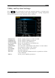

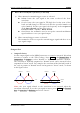

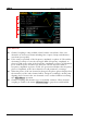
Table Of Contents
- Guaranty and Declaration
- Safety Requirement
- DG1000Z Series Overview
- Document Overview
- Chapter 1 Quick Start
- Chapter 2 Front Panel Operations
- To Output Basic Waveform
- To Select Output Channel
- To Select Basic Waveform
- To Set Frequency/Period
- To Set Amplitude/High Level
- To Set Offset/Low Level
- To Set Start Phase
- Align Phase
- To Set Duty Cycle (Square)
- To Set Symmetry (Ramp)
- To Set Pulse Width/Duty Cycle (Pulse)
- To Set Leading/Trailing Edge Time (Pulse)
- To Enable Output
- Example: To Output Sine Waveform
- To Output Arbitrary Waveform
- To Output Harmonic
- Modulation
- Sweep
- Burst
- Counter
- Store and Recall
- Utility and System Settings
- To Install the Option
- To Lock the Keyboard
- To Output Basic Waveform
- Chapter 3 Remote Control
- Chapter 4 Troubleshooting
- Chapter 5 Specifications
- Chapter 6 Appendix
- Index

RIGOL Chapter 2 Front Panel Operations
2-88 DG1000Z User’s Guide
2. Output Impedance
The output impedance setting influences output amplitude and DC offset. The
instrument has a 50Ω fixed serial output impedance for the [CH1] connector at
the front panel. If the actual load is different from the specified value, the
voltage level displayed would not match the voltage level of the device under
test. To ensure correct voltage level, the load impedance setting must match the
actual load.
Press Utility Channel Set Output Set Imped to select “HighZ” or
“Load”. The default is “HighZ”. If “Load” is selected, use the numeric keyboard to
set specific impedance value. The default is 50Ω and the available range is from
1Ω to 10kΩ. Impedance setting will be displayed on the screen.
The generator will adjust the output amplitude and offset voltage automatically
once the impedance setting is changed. For example, the current amplitude is
5Vpp. At this point, change the output impedance from 50Ω to HighZ and the
amplitude displayed on the screen will double to 10Vpp. If the output impedance
is changed from HighZ to 50Ω, the amplitude will reduce to half of the previous
value (2.5Vpp). Notice that only the displayed values change with the parameter
and the real output from the generator does not change.
3. Output Mode
Set the output mode of the [CH1] connector as normal or gated. In gated mode,
the output state of the [CH1] connector is controlled by the signal from the
[CH1/Sync/Ext Mod/Trig/FSK] connector at the rear panel. When “Gated”
is selected, press “Polarity” to select “Pos” or “Neg”.
Positive: the [CH1] connector ouputs signal when the gated signal is high
level.
Negative: the [CH1] connector ouputs signal when the gated signal is low
level.
4. Range
Press Utility Channel Set Output Set Range and select “Auto” or
“Hold”.
Auto: the generator selects the best settings for the output amplifier and
attenuator automatically.
Hold: disable the automatic optimization, which can eliminate the
discontinuation of the waveform caused by the relay switch when changing
the amplitude but may affect the amplitude accuracy.
5. DDS Hold
Press Utility Channel Set Output Set DDS Hold and select “OFF” or
“ON”. This setting enables or disables the DDS hold function of CH1 and CH2 at
the same time. When DDS hold function is enabled, DDS still works when
turning the output of CH1 or CH2 off. It makes that the phases of the two
channels is synchronized when re-turning the output of CH1 or CH2 on.