
User Manual


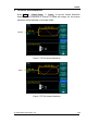


Table Of Contents
- Safety Notices
- The Introduction of DG3000 Series
- Getting Started
- Operating Your Generator
- Application & Examples
- Example 1: To Generate a Sine Wave
- Example 2: To Generate a Square Wave
- Example 3: To Generate a Ramp Wave
- Example 4: To Generate a Pulse Wave
- Example 5: To Generate a Noise Wave
- Example 6: To Generate an Arbitrary Waveform
- Example 7: To Create an Arbitrary Waveform
- Example 8: To Generate an AM Waveform
- Example 9: To Generate an FSK Waveform
- Example 10: To Generate a PWM waveform
- Example 11: To Generate Linear Sweep
- Example 12: To Generate a Burst Waveform
- Prompt messages & troubleshooting
- Specifications
- Appendix
- Index

RIGOL
© 2006 RIGOL Technologies, Inc.
User’s Guide for DG3000 Series
2-65
To Set the Sync Output
The Generator provides Sync output through the [Sync] Connector on the Front Panel.
All standard output functions (except DC and Noise) have a corresponding Sync
Signal. For some Sync applications, they can be disabled if users do not want to use
them,
In the default setting, the Sync Signal should be connected to the [Sync]
Connector (activated). When the Sync Signal is disabled, the output Voltage of
the [Sync] Connector is Level Low.
In the Inverse Mode, the Waveform that corresponds to the Sync Signal does not
Inverse.
For Sine, Square, Ramp and Pulse Signal, the Sync Signal is a Square Signal with
50% Duty Cycle. When the output is positive, The Sync Signal is TTL Level High
compared to 0 V Voltage or DC Offset; when the output is negative, The Sync
Signal is TTL Level Low compared to 0 V Voltage or DC Offset.
For Arbitrary Waveform, the Sync Signal is a Square Waveform with 50% Duty
Cycle. At the time when the first output waveform point is generated, the Sync
Signal Voltage is TTL Level High.
For Internal Modulating AM, FM and PM, the Sync Signal reference is the
Modulated Signal (not the Carrier Signal). The Sync Signal is a Square Waveform
with 50% Duty Cycle. In the first half modulation period, the Sync Signal is TTL
Level High. For External Modulation, the Sync Signal reference is the Carrier
Signal (not the Modulated Signal). The Sync Signal is also a Square Waveform
with 50% Duty Cycle
For FSK, the Sync Signal Reference is the Hop Frequency, and the Sync Signal is
a Square Waveform with 50% Duty Cycle. For the Hop Frequency, at the hopping
point, the Sync Signal is TTL Level High.
For a Sweep which disables the Mark function, the Sync Signal is a Square
Waveform with 50% Duty Cycle. When the Sweep starts, the Sync Signal is TTL
Level High and turns Low at the Center of the Sweep. The Sync Frequency equals
the specific Sweep time. For a Sweep that enables the Mark Function, the Sync
Signal is TTL Level High at the beginning of the Sweep and turns Low at the Mark
Frequency.
For the Burst, when the burst starts, the Sync Signal is Level High. At the specific
point when the Cycle Number ends, the Sync Signal turns Level Low (If the
Waveform has a relative starting phase, it may be not zero intersections). For an
infinite burst, the Sync Signal is the same with the Sync Signal of the continuous
Signal.