
Quick Start Guide


RIGOL
Quick Guide for DG5000
11
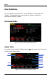
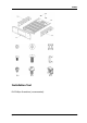
1. DIGITAL OUTPUT
Connect the generator with the “logic signal output module” DG-POD-A
(optional). Then, configure specific sequence digital signal in the generator and
output the signal through the digital module.
2. CH1 Mod/I Signal In (Mod/I1)
This SMB connector accepts an external Analog modulation signal or In-Phase (I)
baseband signal to be used in CH1’s modulation. The nominal input impedance
is 10 kΩ.
3. CH2 Mod/I Signal In (Mod/I2)
This SMB connector accepts an external Analog modulation signal or In-Phase (I)
baseband signal to be used in CH2’s modulation. The nominal input impedance
is 10 kΩ.
4. CH1 Q Signal In (Q1)
This SMB connector accepts an external Analog/ Quadrature Phase (Q)
modulation signal to be used in CH1’s modulation. The nominal input impedance
is 10 kΩ.
5. CH2 Q Signal In (Q2)
This SMB connector accepts an external Analog/ Quadrature Phase (Q)
modulation signal to be used in CH2’s modulation. The nominal input impedance
is 10 kΩ.
6. CH1 Sync Out (Sync1)
This SMB connector outputs a TTL-compatible pulse synchronized with the
output of CH1. The nominal source impedance is 50 Ω.
7. CH2 Sync Out (Sync2)
This SMB connector outputs a TTL-compatible pulse synchronized with the
output of CH2. The nominal source impedance is 50 Ω.
8. CH1 ExtTrig In (ExtTrig1)
This SMB connector accepts an external TTL-compatible pulse as the trigger
input of CH1. Besides, it can also be used as the trigger out in Sweep and Burst
mode.